


Contributing Writer

Figure 1: An example of a simple cutting table sets the table for discussion on just how this is to be modeled.
This month we continue with the cutting table project. Last month we started the project by modeling a subpan, side rail, and leg. The models for the hardware were obtained from online CAD libraries. A circular pattern of components resulted in an assembly with four legs, four side rails, and 16 nuts and bolts as shown in Figure 1.
One more quick reminder: Some of the verbiage used in the discussion of CAD modeling in this column is unique to the software I’m using. However, you will find that other software offers similar functionality in most instances, even if wording and commands are different than those mentioned here.
As an overview, we are going to create an exploded view of the table, which will be useful when preparing the assembly instructions. We probably will use it on the bill of materials (BOM) drawing too. We also are going to do some data entry so that the correct information shows up in the BOM table.
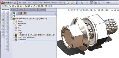
Before delving into the process of creating an exploded view, I should explain that I used a shortcut when putting the hardware into the virtual prototype. One of the tricks I used was to make a subassembly consisting of a nut and a bolt (see Figure 2). Within that subassembly, I mated the nut concentric with the bolt to set the proper clamping distance of the nut and bolt. You may notice in Figure 2 that the file names and descriptions for the components appear in the Feature Manager. That is the way I have my Tree Display options set, and it works well if the proper data entry gets completed. We’ll delve deeper into that later.
In the virtual prototype, I inserted one instance of the nut and bolt subassembly and mated it to a hole in the leg with the head against the outside surface of the leg. I had modeled the holes in the leg using the Hole Wizard, so I was able to create a Feature Driven Pattern of the subassembly to put two sets of nuts and bolts in one leg. I then mirrored that pattern for the other leg and, as a result, filled in all four bolt positions on one side of the table. A 4x circular pattern of that 4x pattern filled in the 16 nuts and bolts for the entire assembly.
While that shortcut minimized the number of times that I had to insert a bolt and a nut—once instead of 32 times—and also minimized the number of mates I had to create to get the hardware to go into the proper holes, the shortcut has some consequences for creating exploded views. This will be important when it comes time to decide whether to explode the subassembly as an assembly or as individual parts.
To create an exploded view in an assembly, I go to the top of the Feature Manager (see Figure 3a) and click to display the Configuration Manager. I can then right-click the mouse button on a configuration name and then left-click the mouse button to create a new exploded view. I tried to show the two clicking steps in Figure 3b.
The process of creating explode steps is pretty straightforward: Click on a component to light up its arrows and then drag the appropriate arrow in the direction and distance you desire. You can select several components in a single step to move them all at the same time.
I have found that it is good practice to create explode steps in pretty much the same sequence that you’d follow when actually taking apart the real assembly. My reason for this is that l might want to create an animation later showing the table putting itself together. It is slightly less work to do that if the explode steps are in the right sequence to start with.
I also think it is good practice to move groups of related components in a single step and then add steps to further explode that group. This is partly for the same planning for animations, but it also makes it somewhat easier to edit the explode when fine-tuning the spacing of things in the final result.

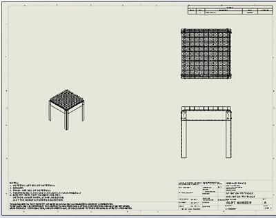
Figure 7c: The exploded isometric view on the drawing is now complete.
Many CAD systems allow for selections of groups of objects by using the mouse to identify two opposing corners of the desired selection region. The idea is to click and drag. Where you click defines one corner of the selection rectangle, and as you drag, the selection region dynamically changes shape. The point at which you release the mouse sets the second corner of the selection window. The direction of the drag relative to the click is important: It sets how objects are selected. Drag to the right and up to select only the objects that completely fit inside the selection rectangle, or drag to the left and down to select anything that is touched or inside the selection rectangle.
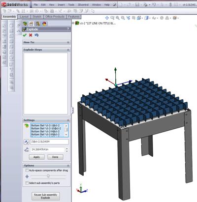
In this cutting table example, I’m going to select all of the top slats and move them in a single explode step. To select them all, I positioned the model on the right view and drew a selection rectangle to include only and all of the slats. If I miss a few, I can add them to the selection group by holding down the CTRL key and then left-clicking on the face of an object to toggle it in or out of the selected group. Once a selection has been made, it is highlighted and its name appears in the Settings list. You’ll also see the explode drag handles appear as shown in Figure 4.
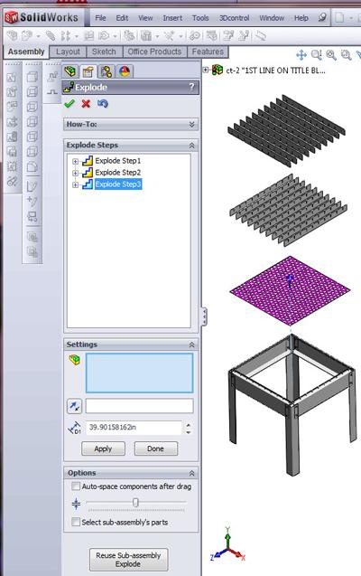
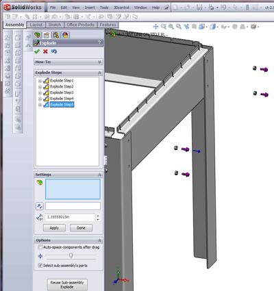
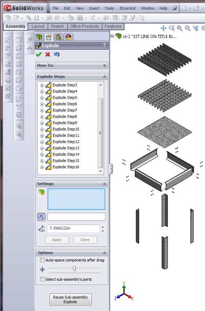
In Figure 5a, the Explode Step 2 moves the upper slats away from the lower slats. Explode Step 3 moves the subpan out of the table frame. In Figure 5b, I’ve zoomed in to be able to select the nuts and bolts more easily on one side of the table. Note that when a subassembly is selected, all of its components will move together unless you click to select the Select subassembly’s parts option.
In Figure 5c, I’ve selected that option to move the bolts away from the nuts. You can toggle this setting for each step as you create or edit the step. Finally, in Figure 5d, we see the completed sequence of explode steps. Once you’re satisfied with the appearance of the exploded view, click the green check mark to dismiss the Explode Property Manager. To edit the explode, just right-click the mouse button on the ExplView1 feature and select Edit Feature. If you double-click on ExplView1, the assembly will toggle from explode to collapse.
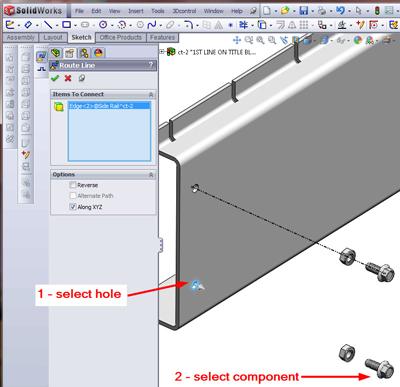
It isn’t always easy to see how things connect, so it might help to add an exploded line sketch. In Figure 6, I’ve already started the Explode Line Sketch tool. Either click Insert> Explode Line Sketch from the menu or use the icon on the Assembly Command Manager.
The process is straightforward:
Once you get the line you like, click the little green check mark. You can then add another line or click the big green check mark to dismiss the Route Line Property Manager.
In Figure 7a, I’ve made a new drawing from the assembly and put in an isometric view. I want this view to show the assembly in an exploded state. To do that, right-click the mouse button as the arrow hovers over the view and select Properties. That launches the Drawing View Properties dialogue shown in Figure 7b. Select the Show in exploded state check box, and then click on OK. The view should explode as shown in Figure 7c.
Next month we’ll take a look at inserting a BOM table into this drawing and completing the data entry to make it accurate. As a heads-up, we’ll be using file properties to store the data that will display in the BOM table. We’ll examine several methods for completing the data entry, including the File>Properties functionality built into all Windows documents; direct entry of data in the BOM table; and the ever-so-useful Property Tab Builder. We’ll use it to create custom data entry forms that pretty much goofproof the process.
Gerald would love to have you send him your comments and questions. You are not alone, and the problems you face often are shared by others. Share the grief, and perhaps we will all share in the joy of finding answers. Please send your questions and comments to dand@thefabricator.com.


The Fabricator is North America's leading magazine for the metal forming and fabricating industry. The magazine delivers the news, technical articles, and case histories that enable fabricators to do their jobs more efficiently. The Fabricator has served the industry since 1970.
start your free subscription
Easily access valuable industry resources now with full access to the digital edition of The Fabricator.

Easily access valuable industry resources now with full access to the digital edition of The Welder.

Easily access valuable industry resources now with full access to the digital edition of The Tube and Pipe Journal.

Easily access valuable industry resources now with full access to the digital edition of The Fabricator en Español.
Cameron Adams of Laser Precision, a contract metal fabricator in the Chicago area, joins the podcast to talk...


