


Contributing Writer
Figure 1a
The industrial design team created a cardboard mockup showing the overall look and operation of the coffee brewer.
Disclaimer: This case study of a sheet metal cabinet features a pair of inventors doing their best without the benefit of experience in manufacturing.
The previous edition of this column (“A 3-D CAD modeling case study: Focus on industrial design limits attention paid to future manufacturability,” Precision Matters, The FABRICATOR®, February 2018, p. 46) discussed the evolution of a cabinet’s design for a commercial coffee maker. The initial focus was on the industrial design (see Figure 1a).
Now the task is to make it real. The must-retain features from industrial design included the wide box in the front and a narrower box in the rear. The mockup shown in Figure 1a relied on rough estimates for what would be installed inside the cabinet. Power supplies, practical sizes for glass, and removable panels for service changed the design (see Figure 1b).
The CAD model shown in Figure 1b was intended to bridge the gap between industrial design mockup and a final design optimized for manufacturing. The industrial designers approved all the differences found in Figure 1b that didn’t exist in Figure 1a.
There is a definite connection between the initial industrial design and the resulting plan for production. This is a good thing and is not as easy to accomplish as it may sound. If the team involved with design for manufacturability (DFM) is not in tune with the industrial design goals, misdirected effort may result, but that’s a theme we’ll cover in a future edition of this series.
Because of time constraints, related to a deadline for delivering a functioning coffee maker model to a tradeshow, the CAD model sent to manufacturing reflected a lot of expert guesswork. The sheet metal cabinet was basically a hollow shell to show where seams and welds and bolts needed to be. For interior planning, almost nothing was modeled. The components that filled the cabinet were known, literally, as physical prototypes that were set up on a bench.
Using a tape measure, the DFM team estimated where the relays and power supplies could mount. There wasn’t time or perceived need for a bill of materials (BOM) in CAD.
A frequent theme of Precision Matters has been virtual prototyping in CAD and generating the resulting BOM. A small tragedy in this coffee tale is the lack of time to fully model the machine’s guts. As another bit of foreshadowing, we’ll savor the glory of a complete prototype and BOM in a future edition. For now, we sense dread as our heroes prepare to place contracts for custom-made glass, sheet metal, spun bowls, and machined parts. “We’ll figure it out later” is oft said in their lab.
A major joy in this tale is the expertise in machining that the DFM team had. In addition to sheet metal, components included a control tablet and glass bottles that plug into plastic nozzles. These machined parts were modeled in enough detail that STEP files could be used for costing and fabrication.
The DFM team included a local expert in glassware. He produced samples before drawings could be made. The certainty in glass bottles led to a good design for the mating sockets. That in turn led to the size of things that the sheet metal box needed to cover. The resulting sheet metal cabinet is shown in Figure 2a.
Figure 1b
The initial design was modified to suit components that were not available during the industrial design stage. Even though some dimensions changed, the overall look is very similar to the original.
As machinists, they knew enough to know that they didn’t know enough about sheet metal. Basically, sheet metal was a black art, so the DFM team did their best to represent what the finished case would look like, not necessarily how to make it.
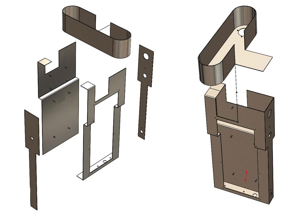
In Figure 2b we see the three major “boxes” along with several covers, hinged doors, and a slide-out tray.
The CAD planning included weld studs that would connect the three boxes to form a rigid framework. The covers were to be held in place with sheet metal screws. The screw size and sheet metal thickness were details that would be delegated to the manufacturing crew.
From a fabrication point of view, the CAD plan had several gaps. For example, consider the box shown in Figure 3a. The good news is the 3-D sheet metal parts resemble actual sheet metal. Even though the 2-D drawings are lacking, the 3-D model shows the locations of weld studs and holes required for assembly. The grim news—the sheet metal parts in Figure 3b are held together with mystery. The method of welding and cosmetic finishing again would be delegated to the manufacturing crew.
Manufacturing also would figure out grain direction and how to make the door hinges fit.
Our heroes had several reasons for delegating so much responsibility to manufacturing. Their expertise in coffee did not translate into expertise in sheet metal fabrication. They did not need more than a few of these enclosures. Future builds almost certainly were going to change. This project was intended primarily to make a good impression at a tradeshow.
Most important, the schedule dictated “paperless” manufacturing. If this could get built without expending time producing 2-D drawings, then that would be best. As far as quality control, revision management, and document management were concerned, if the box fit together and resembled the CAD, it would be acceptable.
In the best outcome, three different manufacturing crews would apply their expertise to fabricating this cabinet. Future design work can use the best of these ideas for the product that goes into mass production. At a minimum, at least one of the three bidders will make the promised deadline.
The CAD model was distributed to several sheet metal job shops and three responded with price quotes for one-offs based on what they understood from the STEP file. It was comforting that all bids came in within 10 percent of each other. (You may be familiar with a “Franklin” as a $100 bill. Each of the shops asked for a “Chase,” as in Salmon P. Chase, secretary of the U.S. Treasury from 1861 to 1864, who happens to grace the $10,000 bill.)
As a cliffhanger for the next episode, we leave a happy thought: A machine was shown successfully at the tradeshow. Years have passed, and our heroes are still in business.
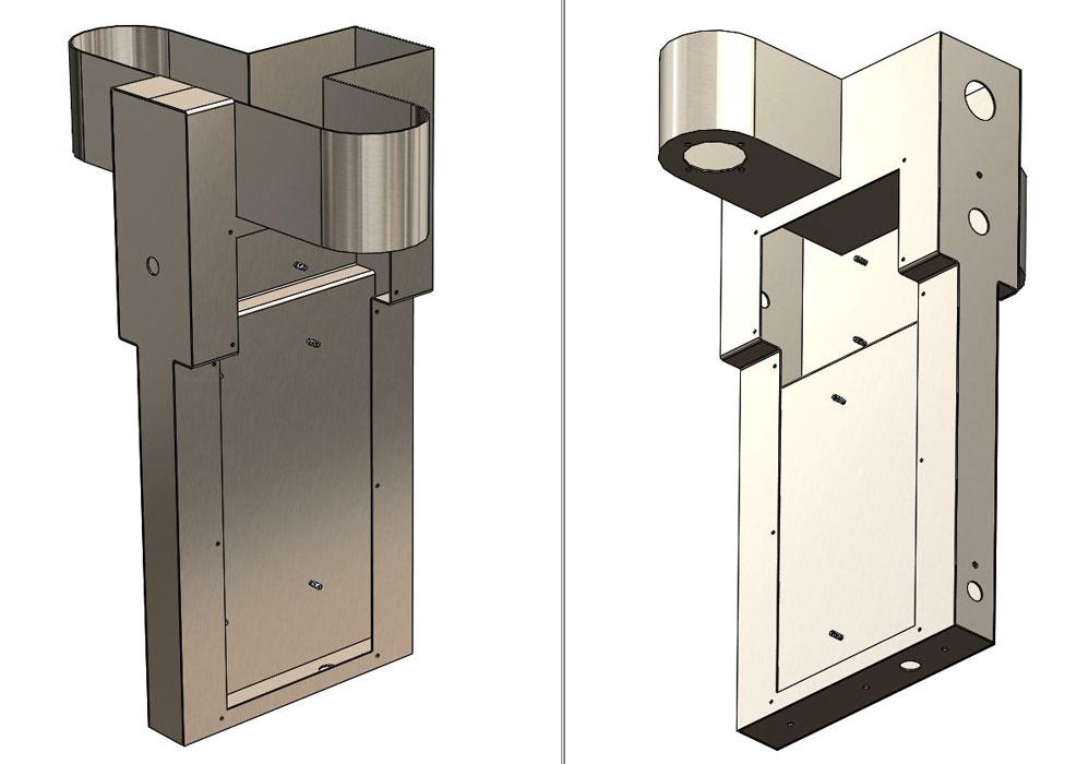
Figure 2a
The sheet metal cabinet model shows the location of vents, service panels, doors, and slides.
How would you have responded to this RFQ? What would happen to all of the “delegated” stuff—the drawings, fixtures, and tooling?
Gerald would love for you to send him your comments and questions. You are not alone, and the problems you face often are shared by others. Share the grief, and perhaps we will all share in the joy of finding answers. Please send your questions and comments to dand@thefabricator.com.


The Fabricator is North America's leading magazine for the metal forming and fabricating industry. The magazine delivers the news, technical articles, and case histories that enable fabricators to do their jobs more efficiently. The Fabricator has served the industry since 1970.
start your free subscription
Easily access valuable industry resources now with full access to the digital edition of The Fabricator.

Easily access valuable industry resources now with full access to the digital edition of The Welder.

Easily access valuable industry resources now with full access to the digital edition of The Tube and Pipe Journal.

Easily access valuable industry resources now with full access to the digital edition of The Fabricator en Español.
Seth Feldman of Iowa-based Wertzbaugher Services joins The Fabricator Podcast to offer his take as a Gen Zer...


