


Contributing Writer
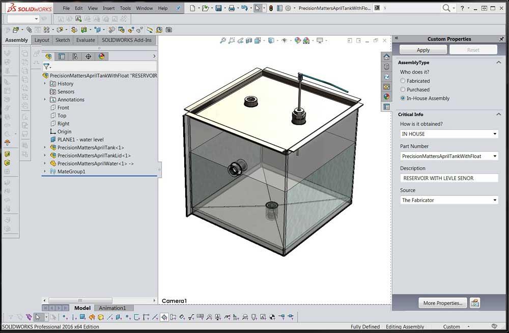
Figure 1
This water tank is the start of a product line of water tanks. This model was introduced in the April episode.
Editor's Note: If you would like to download the 3-D CAD files associated with this column, click here.
The CAD project shown in Figure 1 was introduced in the April 2017 edition of this column (“Shop technology and 3-D CAD: Translating design goals into CAD techniques,” The FABRICATOR, p. 40). Rick S. from Montreal sent this musing to the author: “How would I build this parametrically if I had seven different sizes to make in one shot and if I wanted to be able to respond to a client’s specific dimensions in minutes?”
Rick went on to outline an idea he had for avoiding the use of configurations to drive the tank. He wondered how the author would approach this problem.
The short answer is, while inventing and developing the design, I would use some combination of parametric links and configurations. I would try to model for quick-switch visualization only if it speeds the design to market. When the design is ready for market, I would branch the configured CAD models into stand-alone single-configuration assemblies. To match purchasing, I would maintain shared/configured CAD models for hardware items in the product line.
From a parametric planning point of view, the water contained in this tank sits inside a piece of equipment. The CAD jockey can deem one of those—water, tank, or equipment—to be the “controlling feature.”
To represent the equipment, we could set up reference geometry in the form of planes, sketches, or surfaces. Using that work flow, always sketch or extrude to the relative locations of the reference geometry. By changing the position of the reference geometry, you change the size of the parametrically driven model. The trick is for the CAD jockey to move the reference geometry with ease.
The project from April uses the tank, specifically the sheet metal tank wall frame, as the controlling feature. The floor changes size to match the wall. This is the same with the lid. The water fills the tank to the specified head room.
This article outlines a work flow for controlling variations in a product’s design using a combination of parametric links and configuration-driven features. Undoubtedly, several better solutions are available to do just this, but are not discussed here. The general recommendation is to identify the variables and their range of values throughout the product line and then select the best modeling technique for that design intent.
A Configuration Table (see Figure 2) allows a single CAD model to represent several SKU items. In this example, a model of a washer has been configured for nine different sizes. This Configuration Table is controlling the thickness, inside diameter, outside diameter, and part number for each washer size.
This ability for one file to be many things offers several advantages:
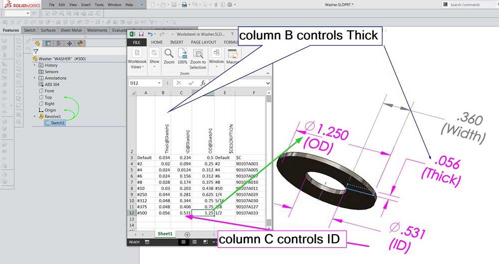
Figure 2
A washer is modeled with a revolved sketch. The dimensions are given meaningful names for convenience. A Configuration Table is inserted. A dimension is entered as a heading in a column, and values are entered in the rows for each size of washer.
Configurations can be created without using a Configuration Table. The Configuration Table is a recommended technique and adds convenience to creating and editing configurations.
Another useful application of configurations as a CAD work flow is the ability to switch from one product to another. This water tank is a practical example of a single model representing three products with a handful of features that make them distinctive.
Here is a CAD tip: Configuration Tables that are switching multiple details can be challenging for a future CAD jockey to understand quickly. For long-term maintenance purposes, when more than a handful of variables change between products, you would probably be wiser to use separate files instead of Configuration Tables.
Planning, in this scenario, involves identifying the variables in the design that we need to control. A quick jot of notes—taken from imagined design planning meetings—reveals that to quickly switch between product lines we need to control values for three variations of floor XY sizes, tank Z height, and head-room distances.
We want the model of the water to accurately reflect the interior of the tank as the size of the tank changes. Planning also tells us that a few items (the 0.25-in. British Standard Pipe Thread, a sensing probe, and the 90-degree corner shape) must remain constant in our product line.
Using these meeting notes, we prepared a planning spreadsheet for CAD use (see Figure 3 and the yellow highlight). Whether we use a spreadsheet, a doc, or a pencil and paper, the recommendation is to record the location of variables in the model that will have to change in the product line.
For the features that must not change, rows eight, nine, and 10 in this spreadsheet serve as a check list. The model for each feature that must not change size is to be inspected by the CAD jockey to verify no untoward parametric links.
Here’s a CAD tip: The completion of a planning spreadsheet, such as Figure 3, is a good point to decide on a CAD modeling technique for quickly switching between products. Some work flows to consider include separate (stand-alone) assembly models, configuration-driven models, and property- or value-driven models.
A value-driven model was introduced in April to address the last work flow possibility. We offer a download of the CAD model this month for your detailed review. (Visit www.thefabricator.com/page/shop-technology-and-3-d-cad-downloads). Parametric links driven by the size of the wall model cause the floor and water to change shape. A data entry form can be set up using Custom Property Builder to allow the values to be typed in like a web form.
The stand-alone modeling work flow was also hinted at in April. The CAD system’s Pack & Go tool is very useful for branching projects into new files and folders while maintaining common parts between the projects.

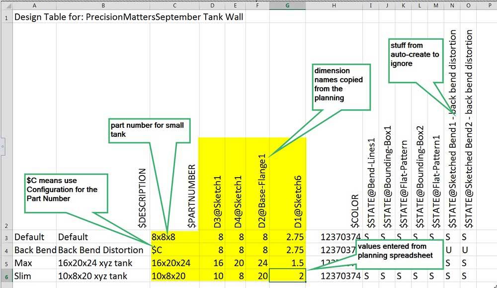
Figure 3
Planning the product line starts with documenting the first product. Values from the Default configuration found in the April model were entered in rows 1 through 10 and subsequent rows were updated. The most important task: Identify where and what needs to be controlled and changed during the quick switch between designs.
The configuration-driven model work flow is a good one. Configurations have behaviors—convenience of editing and ease of insertion/removal—that simple parametric links lack. Table-based designs can be a blessing for long-term maintenance. Adding configurations to the water tank product line’s model is largely a two-step process:
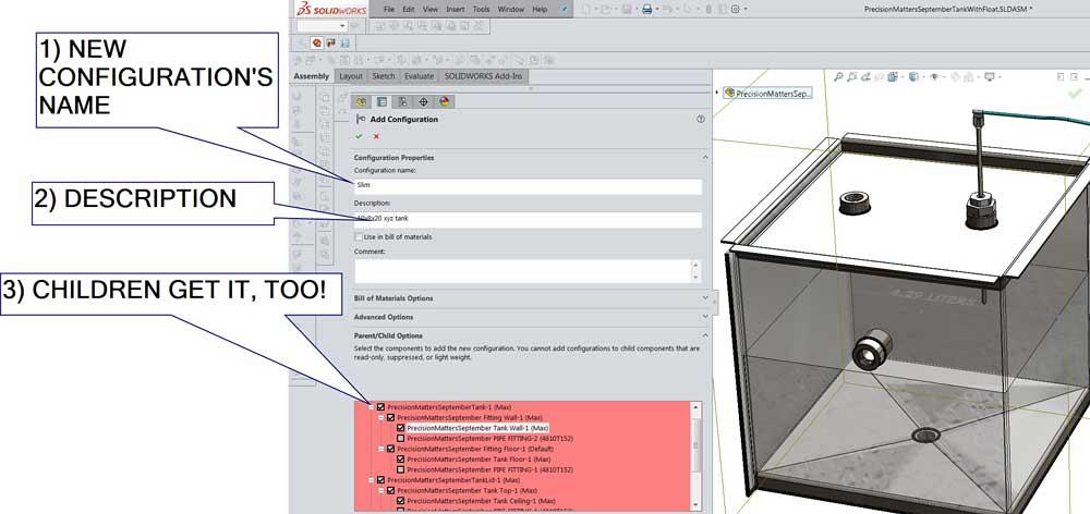
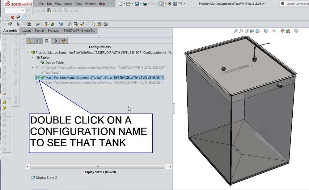
1. Add configurations to the top-level assembly—and its children too (see Figure 4). This allows for quick switching between products. All that is needed is just a double-click on the configuration name.
2. Insert a Configuration Table into the top-level assembly (see Figure 5). This allows for sizes of things to be selected, items to be added or removed, and colors to be changed.
(If you add the configurations to the children as shown in Figure 4, the parents and children will have coordinated behavior. For each configuration in the top level, all of the children will switch to the correct configuration. Other work
flows for adding configurations can be used, but they involve many more steps to coordinate the children.)
Here’s a CAD tip: The Configuration Table Auto-create tool has useful default settings. Those were used as a starting point for Figure 5. The information in yellow highlight was copied from the planning spreadsheet. Excel likes to make hyperlinks out of dimension names. Right-mouse-click in the cell and select Remove Hyperlink. Then use the Format Painter to match the text alignment.
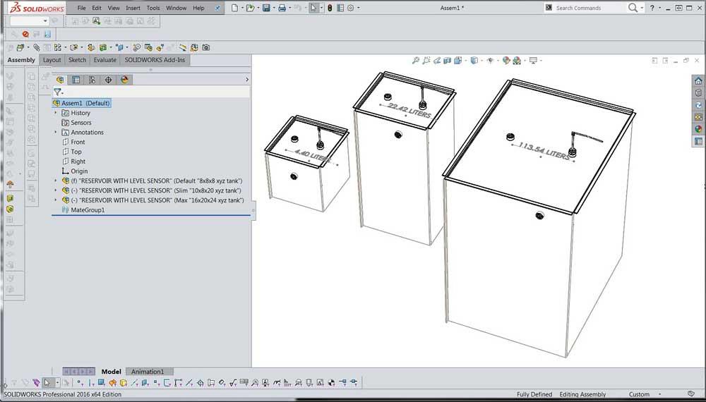
The finished product line of tanks is shown in Figure 6. To show the differences between tanks, each of the three has a different configuration selected: Default, Slim, or Max.
For live presentation of the product line, open the tank assembly and click through the configurations. Figure 7 shows the tank in the Max size.
Disclaimer: It took more than a few mouse clicks to get the April model ready for the September configurations. The April CAD model keeps both walls the same size. Rectangular tanks didn’t happen in April, so that constraint was removed in the September revision. The floor and lid had their parametric constraints updated for rectangular variations. The cross break in the floor required three separate forming tools (suppressed unless needed). And finally, the model for the water is not entirely faithful; a shortcut was taken for the author’s convenience, and it does not report the fluid inside or above the bottom fitting.
Gerald Davis uses CAD software to design and develop products for his clients at www.glddesigns.com. From 1984 to 2004 he owned and operated a job shop.
Gerald would love for you to send him your comments and questions. You are not alone, and the problems you face often are shared by others. Share the grief, and perhaps we will all share in the joy of finding answers. Please send your questions and comments to dand@thefabricator.com.


The Fabricator is North America's leading magazine for the metal forming and fabricating industry. The magazine delivers the news, technical articles, and case histories that enable fabricators to do their jobs more efficiently. The Fabricator has served the industry since 1970.
start your free subscription
Easily access valuable industry resources now with full access to the digital edition of The Fabricator.

Easily access valuable industry resources now with full access to the digital edition of The Welder.

Easily access valuable industry resources now with full access to the digital edition of The Tube and Pipe Journal.

Easily access valuable industry resources now with full access to the digital edition of The Fabricator en Español.
Seth Feldman of Iowa-based Wertzbaugher Services joins The Fabricator Podcast to offer his take as a Gen Zer...


