


Contributing Writer
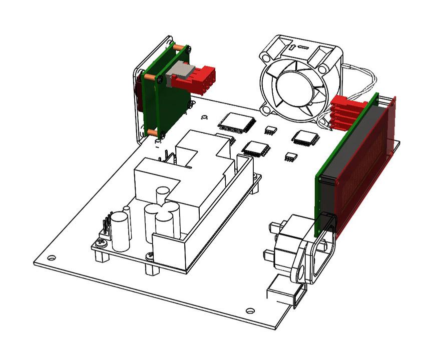
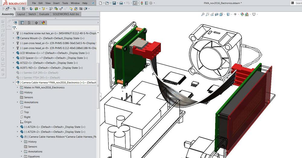
Figure 1
An electronic module with a camera (on the upper left) and a controller (on the right) is shown. A model of a cable is needed to connect between the red plugs.
Editor's Note: If you would like to download the 3-D CAD files associated with this column, click here.
When creating visually credible models, it helps to include cables and plugs. A model for a twisted pair of wires was discussed in the previous edition of this column (“Shop technology and 3-D CAD: Modeling a cable harness,” The FABRICATOR, October 2016, p. 60). In addition to looking pretty, such detailed models may contribute to improved mechanical and electrical design.
Figure 1 shows an electronic assembly that includes a camera and a controller. They do not yet have wires connecting between them. As a technique for modeling such a harness, a subassembly containing the two red plugs and the to-be-modeled wires will be created.
This provides an outline of the CAD technique being recommended:
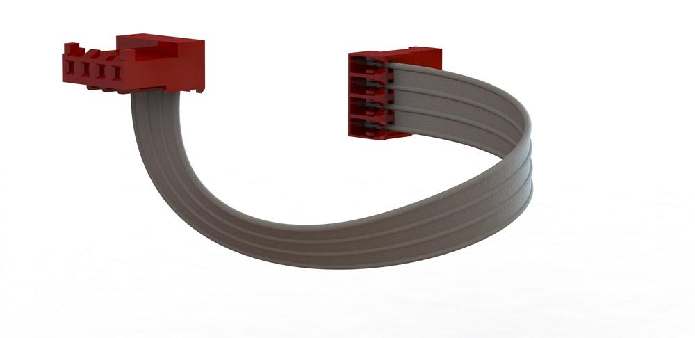
Figure 2 shows the CAD details behind the ribbon cable’s sweep. The major difference between this sweep and that discussed in the October issue is the shape of the wire harness. In this example, a ribbon cable profile sketch is modeled instead of a pair of leads. The path is still a combination of straight lines and a spline.
In Figure 3 additional details have been added to the model to represent stripped plastic for insertion into insulation displacement connectors. (If you are into how-it’s-made specifics, the CAD model is available for download at www.thefabricator.com/page/shop-technology-and-3-d-cad-downloads.) Appearing in Figure 3, the CAD technique used to “strip the insulation” involves the creation of a linear pattern of an extruded cut.
Here’s a CAD tip: For modeling similar insulation cuts at the second end of the ribbon cable, use a derived sketch from the cut modeled for the first end.
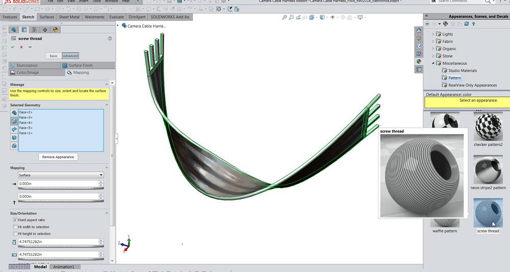
The ribbon cable shown in Figure 3 appears to have conductors running along its interior, even though the profile of the sweep is a simple rectangle with radius ends. This CAD trick applies a “threaded” appearance to strategic surfaces of the sweep. Traditionally, the thread appearance is applied to cylinders to represent screw threads. This CAD trick changes the orientation of the thread to look like wires. Also, the CAD jockey can change the scale of the appearance to change the number of circuits. (Thanks to Phil Sluder for sharing this trick at training sessions during SolidWorks World.)
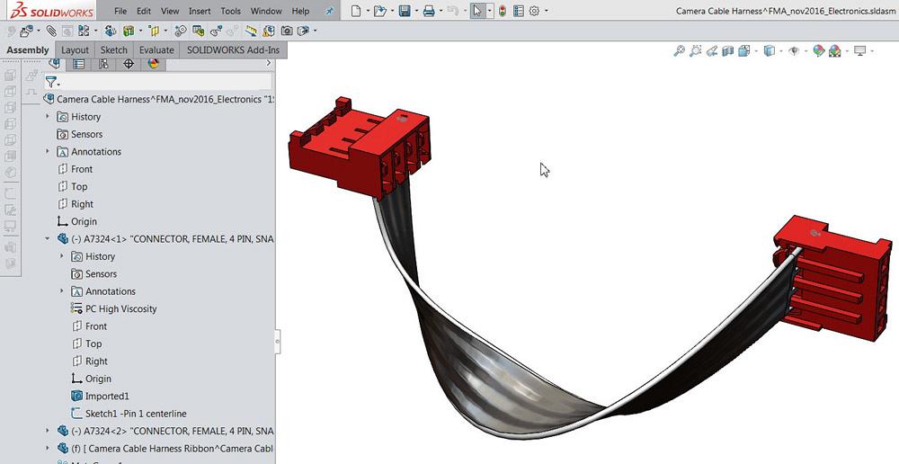
As a CAD technique, the path of the sweep in Figure 2 was constrained to the connectors shown in Figure 4. The setting of twist rate of the sweep allows the ribbon cable’s ends to align with the connectors.
The model for the red connector includes a sketch that aids in constraining to Pin 1 of the circuit, which is just visible in gray lines in Figure 4. This sweep connects Pin 1 to Pin 1. In order to do that, the ribbon cable must twist and buckle. This is not a relaxed component.
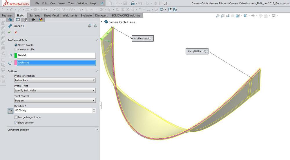
Figure 2
A 3-D sketch has two line segments connected with a spline. At each end, the spline is made tangent and coincident with the line segment. The ends of the lines will be constrained to features on the red plugs.
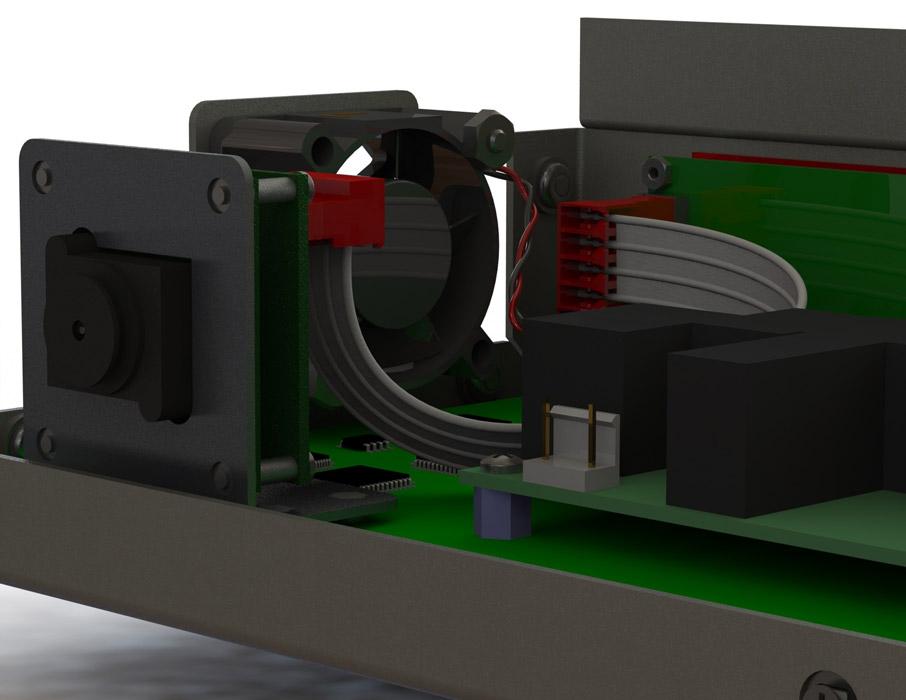
Figure 5 shows the model of the twisted camera cable harness in the context of the electronic component assembly. As the red connectors are positioned in CAD to align with headers on the camera and controller, the model of the ribbon cable will do the right thing and follow the connectors.
Mechanical considerations may affect the schematics for electrical connections, often in mysterious ways. In Figure 6, the electrical circuit for the harness has been changed—relative to Figure 4—because of mechanical problems with twist in the ribbon. Pin 1 is now connected to Pin 4 on the other end. This removes some of the buckling strain from the ribbon cable’s path.
Also new in Figure 6, the profile sketch for the ribbon cable’s sweep has been changed to include the detail of conductors under the insulation. As rendered by Photoview, the ribbon cable looks realistic. Note that the “thread appearance” trick is no longer needed, nor does it work with photorealistic rendering.
As a preview of photorealistic rendering, Figure 7 reflects the finished model for the camera’s cable harness. It is a nice-looking as well as a functional design.
Gerald would love to have you send him your comments and questions. You are not alone, and the problems you face often are shared by others. Share the grief, and perhaps we will all share in the joy of finding answers. Please send your questions and comments to dand@thefabricator.com.


The Fabricator is North America's leading magazine for the metal forming and fabricating industry. The magazine delivers the news, technical articles, and case histories that enable fabricators to do their jobs more efficiently. The Fabricator has served the industry since 1970.
start your free subscription
Easily access valuable industry resources now with full access to the digital edition of The Fabricator.

Easily access valuable industry resources now with full access to the digital edition of The Welder.

Easily access valuable industry resources now with full access to the digital edition of The Tube and Pipe Journal.

Easily access valuable industry resources now with full access to the digital edition of The Fabricator en Español.
Seth Feldman of Iowa-based Wertzbaugher Services joins The Fabricator Podcast to offer his take as a Gen Zer...


