


Contributing Writer
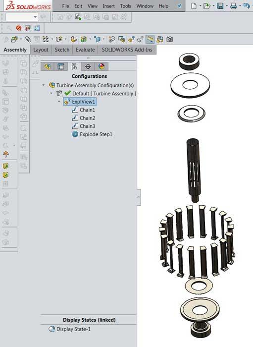
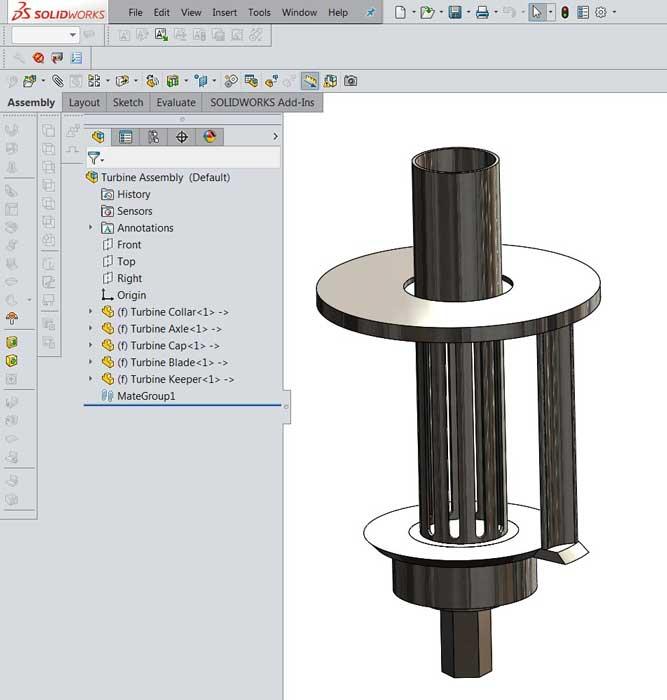
Figure 1
An exploded view of an assembly of 25 components is shown. The 18 blades are identical. Several other components are identical pairs. The center axle is the only unique part. The goal is to create part models for manufacturing; the design for all of these parts is to be controlled with a single sketch.
Editor's Note: If you would like to download the 3-D CAD files associated with this column, click here.
Reader John S. posed this question: “What is the proper way to start a design? Is the world coordinate origin (0,0,0) the best?”
Well, as a general reference point, the world coordinate (0,0,0) is widely understood. Sometimes it’s a time-saving referencing technique. Sometimes the origin is merely a distraction.
The use of the world coordinate system (WCS) is good when components are shared by many projects, perhaps by many CAD systems. For these models, referencing the WCS could be intuitive as well as useful when it comes to positioning the model in an assembly. The ability to define a user coordinate system (UCS) takes the pressure off the CAD jockey who might otherwise want to model with the WCS in mind. Once a UCS has been placed, it may be used as if it were the WCS. It does not matter where the “real” WCS was or is.
The benefits of not relying on the world coordinate origin are most apparent in assemblies of components that share a common design theme: extremely dependent upon parametric links between the components. The CAD technique of splitting parts from a master assembly allows the split parts to be reassembled by mating them all to their common origin, which can be nearly automatic and save considerable CAD labor during the final assembly step.
Splitting components out of a multibody part can be a useful CAD technique and is a good demonstration of a way to avoid concern with the WCS or UCS. The CAD trick of multibody modeling using a shared sketch results in all of the components presenting a common origin.
This is a demonstration of how to model all components to have a common origin. This common origin could be located anywhere. We’re going to locate our sketch using the WCS for convenience. The task is to design a turbine for a pump. Figure 1 shows the finished product in an exploded view of 25 components. The sketch used to model all of those components is shown in Figure 2. This sketch is set up for Contour Select. The April 2017 edition of this column (“Shop technology and 3-D CAD: Translating design goals into CAD techniques,” p. 40) discusses Contour Select in some detail, with the intent of controlling most of the turbine’s features with a single sketch.
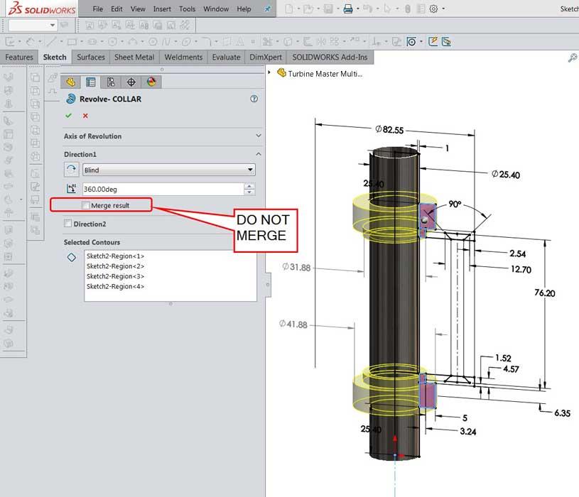
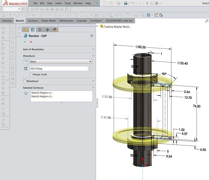
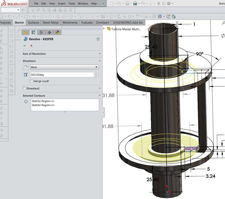
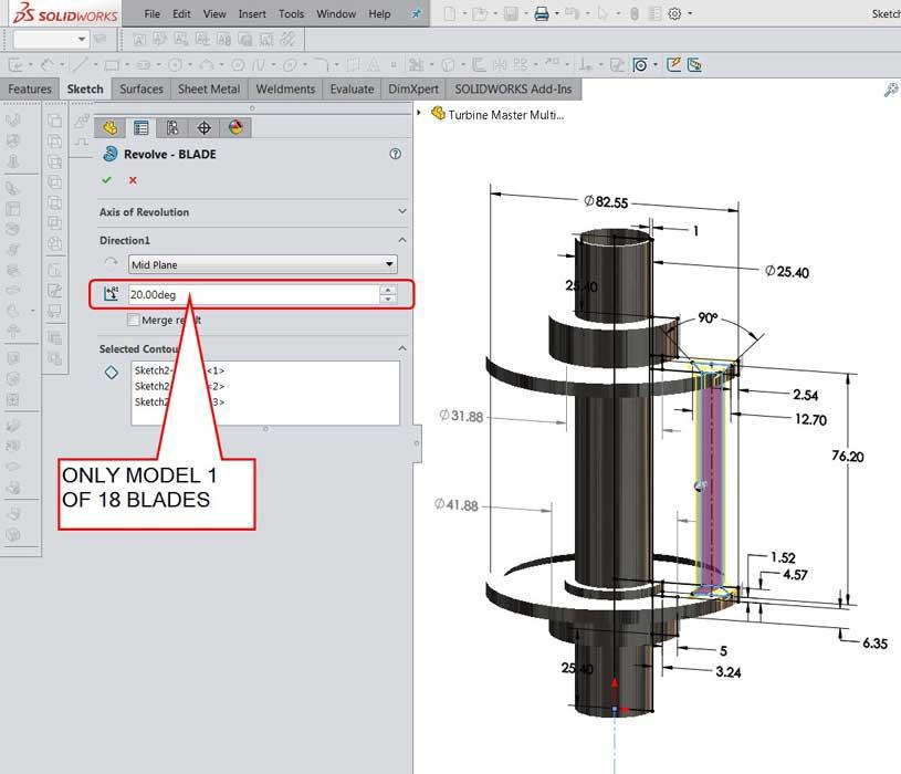
Figure 3a shows the first use of this sketch: to model the axle for the turbine by selecting the contours that belong to it. Figure 3b shows how the sketch can be reused to model the bodies for the collars. Note that Merge Result is turned off so that the axle exists as a separate body from the collars. The process of using the sketch to model bodies is repeated for the end caps in Figure 3c, the blade keepers in Figure 3d, and the blades in Figure 3e. Note that only one of 18 blades has been modeled. The trick is to revolve only 20 degrees to create the width of the blade.
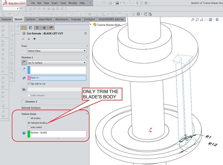
In Figure 4, the fin of the blade is created with a Cut-Extrude. Note that the Flip Side to Cut is in use, which makes it very important to limit the scope of the cut to only the blade’s body.
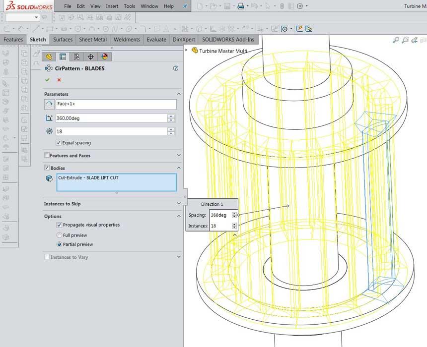
Now that one of the blades is complete, it will be used in a circular pattern to model bodies for the other blades (see Figure 5).
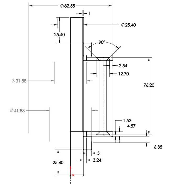
Figure 2
This sketch has contours that represent the profiles of all of the components in the turbine’s assembly. Because all parts are modeled from this sketch, they share the same coordinate system. Here’s a CAD tip: This pretty much eliminates the need for mates in the final assembly.
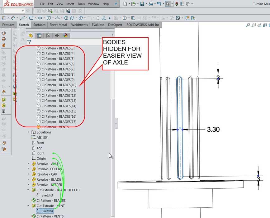
To create a flow path through the turbine, we cut slots in the axle body (see Figure 6). As with the cut to the blade, the scope of this cut to the axle is limited to the axle’s body. When this cut was modeled, the blades were obstructing the view. As shown in Figure 6, they were hidden until the vent cutout was completed. In this example, one vent slot was used in a circular pattern to make 10 cuts.
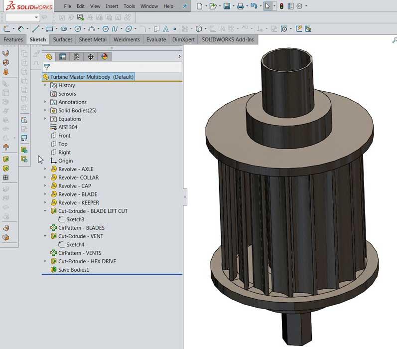
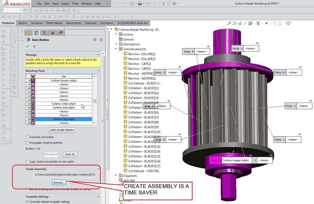
The completed model of the turbine is shown in Figure 7a. This is a multibody part based on one sketch. This could be the final stage in 3-D modeling, but in this scenario we need individual parts for manufacturing and assembly. We want to maintain the single-sketch-controls-it-all idea, so the Save Bodies tool is used to create the separate part models (see Figure 7b).
Note that some of the bodies in this multibody part are identical. We need to save only one of each kind.
Here’s a CAD tip: Double-click in the table to assign good file names to the to-be-created parts. Use the Create Assembly option to accomplish two tasks in one step: Create individual parts and put them together in an assembly.
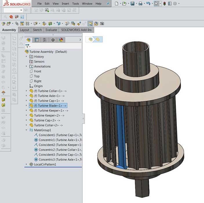
The resulting assembly is shown in Figure 7c. By inserting copies of the missing parts and by creating a circular pattern of blade parts, we can model the complete turbine assembly (see Figure 7d). The exploded view of this assembly is shown in Figure 1.
The Feature Manager shown on the left in Figure 7d reveals how all of the components in this assembly are located. They are fixed in location—an arbitrary origin that we don’t really care about. The relationship between the parts and how they connect together is controlled by the sketch in the master multibody part model. Instead of being fixed, these parts could all be mated to the origin and have the same result, but that’s extra CAD labor. With even more labor, we could replace the fixed mates with concentric and coincident mates to assemble the parts in a “realistic” manner. But the result is the same as leaving the split bodies as they were automatically created.
To review a bit of CAD terminology, mates locate components within an assembly. Mates are applied to restrict degrees of freedom of motion—how components move relative to each other and relative to the world. Each component has 6 degrees of freedom that allow it to tumble in 3-D space. It can rotate about three axes—X, Y, or Z. It also can translate (slide) along those three axes. Mates can connect components together using a variety of features, such as surfaces, edges, points, planes, axis, and faces.
Depending on the design intent, a model might be fully constrained, like a stationary axle, or it might move in a realistic or kinematic way. The mouse can be used to rotate a wheel around an axle perhaps.
Mates that use origin, axis, and plane references might be more robust than mates to surface, edge, or vertex. As the design evolves, faces and edges might disappear, whereas an origin is always somewhere.
Here’s a CAD tip: When you are selecting references, keep the future in mind. In the future another CAD jockey will need to understand how the assembly is connected. Even though a mate to a temporary axis might be easy to create, it might not be easy to understand, especially if that temporary axis is not visible in the future.
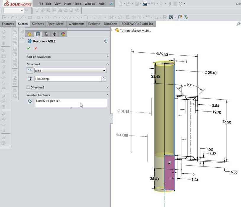
Figure 3a
The contours that belong to the axle are selected to create a solid body.
Perhaps another benefit of locating the WCS at the center of the model is convenience during import into other projects or CAD systems. Drag and drop will follow the mouse pointer. When modeling electronic components for circuit design, e-CAD software uses the world coordinate system by default.
If a user-defined coordinate system named CWX is in the model, the e-CAD software uses that for the origin. A user-defined coordinate system is useful when the world coordinate origin is badly located in the CAD model. This often happens with imported STEP files. User coordinate systems are easy to insert and locate relative to the model.
Specific to a brand of CAD software, when two origins are mated, the CAD jockey has an option to “align axes.” This automatically locks all 6 degrees of freedom in a parallel engagement. It can save CAD labor to be able to fully constrain a component with a single click. As a CAD technique, the user coordinate system is just as handy to use as the WCS for such one-step positioning. Modeling with the WCS in a useful location is simply a CAD technique that minimizes the need for a user-defined coordinate system.
Gerald Davis uses CAD software to design and develop products for his clients at www.glddesigns.com. From 1984 to 2004 he owned and operated a job shop.
Gerald would love for you to send him your comments and questions. You are not alone, and the problems you face often are shared by others. Share the grief, and perhaps we will all share in the joy of finding answers. Please send your questions and comments to dand@thefabricator.com.


The Fabricator is North America's leading magazine for the metal forming and fabricating industry. The magazine delivers the news, technical articles, and case histories that enable fabricators to do their jobs more efficiently. The Fabricator has served the industry since 1970.
start your free subscription
Easily access valuable industry resources now with full access to the digital edition of The Fabricator.

Easily access valuable industry resources now with full access to the digital edition of The Welder.

Easily access valuable industry resources now with full access to the digital edition of The Tube and Pipe Journal.

Easily access valuable industry resources now with full access to the digital edition of The Fabricator en Español.
Seth Feldman of Iowa-based Wertzbaugher Services joins The Fabricator Podcast to offer his take as a Gen Zer...


