


Specifying tolerances to ensure usable fabricated metal parts
How to gain competitive advantage with geometric dimensioning and tolerancing (GD&T)
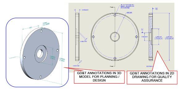
FIGURE 1. GD&T annotations can be placed in most 3D CAD models, as well as on 2D drawings.
Editor’s Note: Read the second part on why datums used in CAD should remain distinct from GD&T datum features.
Geometric dimensioning and tolerancing (GD&T) allows a designer to convey important information about part function to a downstream audience in fabrication, assembly, and quality. Whether the GD&T annotations appear on 2D drawings or are embedded in 3D CAD models, they arm the designer with tools for explaining what is required by either fabrication or quality without forcing inspection of dimensions that, while relevant to fabrication, might not be critical to part function (see Figure 1).
The point of GD&T is usability, and communication of usable information among designers, draftsmen, craftsmen, and inspectors is the key to quality assurance in metal fabrication.
Dimensions and Tolerances
GD&T is a nickname for the formal publication known as ASME Standard Y14.5, Dimensioning and Tolerancing. While it makes for dry reading, the standard’s not difficult to understand. Consider, for instance, its definitions of dimension and tolerance:
- Dimension—A numerical value expressed in appropriate units of measure and used to define the size, location, geometric characteristic, or surface texture of a part or part feature.
- Tolerance—The total amount a specific dimension is permitted to vary. The tolerance is the difference between the maximum and minimum limits.
Perfect versus Perfectly Good
Nominal dimensions are used represent the perfect part. It’s easy to make a perfect CAD model, smooth and friction-free, with ideal roundness and perpendicularity and perfect surface and axis alignment. Such nominal perfection will seldom, if ever, happen in metal fabricating.
You can add hand-crafted tailoring to overcome fit problems. And CNC production methods might be able to automate that fine craftsmanship and perhaps eliminate variation concerns. But while labor and capital equipment might guarantee fit through ultraprecision, the cost of that perfection does not necessarily add value to ownership.
In acknowledgement of reality (and cost), the other option is to add tolerances that indicate how much imperfection is acceptable while maintaining the part’s intended fit and function. Tolerances allow fabricators to produce good, functioning parts without having to be perfect.
There are geometric tolerances and there are plus/minus dimensions. ASME Y14.5 makes an attempt to relegate plus/minus dimensions to a few specific applications. They work well for features of size and might be useful for depth and step dimensions. However, they can cause ambiguity when used to orient, locate, or control the form of part features.
No Part Is an Island
For parts that are completely stand-alone or one-off, the competitive edge of GD&T might be blunt. For parts that will go into an assembly, it’s a different story. With my apologies to John Donne:
No part is an island, entire of itse’f;
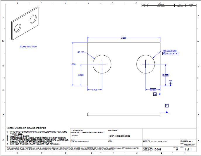
FIGURE 2. Plus/minus dimensions and basic dimensions supporting GD&T tolerances can be mixed on a drawing, but this can create ambiguity and extra costs.
Every part’s tolerance stacks in a nested DRF.*
*Datum reference frame
In an assembly, there is a chain of consequence—a stackup of variations permitted by the tolerances. Deviation of one part must not inhibit overall function of the mechanism, even as other parts in the assembly might also deviate.
So, tolerance specifications are required for the assembly and individually for each of its components. To put that another way, satisfactory function of an assembly does not necessarily indicate interchangeability of its piece parts.
Parts can vary in several ways:
- Within-part variation of a single characteristic
- Deviation of a single part from nominal specification
- Variation of a single part from other (what should be identical) parts.
While those distinctions are challenging to address with just plus/minus dimensions, GD&T is usefully versatile for the task.
Dimension versus Feature Tolerancing
Plus/minus tolerancing is used to tolerance drawing dimensions. GD&T is used to tolerance part features.
Every dimension should have an assigned tolerance. How that tolerance is specified is an opportunity to gain competitive advantage. The tolerance might be shown as a value, a plus/minus, or, within the rules of GD&T, a combination of basic dimensions and tolerance zones (see Figure 2).
Using plus/minus tolerances on dimensions (or using title block default to imply the plus/minus tolerances) is permitted as a drafting technique within ASME Y14.5 (see Figure 3). While plus/minus dimensions can establish the requirements for usability arithmetically, they put a burden on the designer and the fabricator.
Converting, for example, the fit of a pin in a hole into extreme limits for plus/minus dimensions to ensure usability is not a trivial task. And those plus/minus values don’t convey anything about how the part is assembled or used.
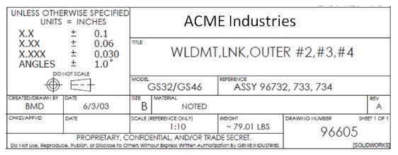
FIGURE 3. This is a typical title block with default plus/minus tolerances that are assigned according to the precision of their dimension.
There is sometimes a feeling that magic will happen if GD&T symbols appear on a drawing, but the “magic” is the result of thoughtful effort. GD&T is a tool that enables the user to say things on the drawing that can be extremely valuable and can lead to the detection and correction of problems before the part can be rejected at assembly.
GD&T can describe the fit of the pin in the hole very clearly. It also can match how the part is used to how the part is measured.
Back to Basics
Basic dimensions locate tolerance zones. They do so with symbols in a feature control frame, expressing the designer’s purest intent. (In GD&T, there are types of dimensions other than basic, such as reference, stock size, min., and max., but these do not define the design.)
There are two main ways to designate dimensions as basic:
- The numerical values can have boxes placed around them (a default or simple mouse-click function in a CAD system).
- A note can be added stating “UNTOLERANCED DIMENSIONS ARE BASIC.” (Be aware that such a note might conflict with legacy plus/minus tolerance default(s) in the title block.)
When a CAD model is used to define part geometry, there should always be a clear note that states “MATH DATA IS BASIC.” This detail provided fabrication with details needed to make the part without burdening inspection with drawing dimensions not needed to assure part function.
Thanks to Gerald Davis, author ofThe FABRICATOR’s “Precision Matters” columns, for his help with the illustrations.
About the Author
About the Publication

subscribe now

The Fabricator is North America's leading magazine for the metal forming and fabricating industry. The magazine delivers the news, technical articles, and case histories that enable fabricators to do their jobs more efficiently. The Fabricator has served the industry since 1970.
start your free subscription- Stay connected from anywhere

Easily access valuable industry resources now with full access to the digital edition of The Fabricator.

Easily access valuable industry resources now with full access to the digital edition of The Welder.

Easily access valuable industry resources now with full access to the digital edition of The Tube and Pipe Journal.

Easily access valuable industry resources now with full access to the digital edition of The Fabricator en Español.
- Podcasting

In this episode of The Fabricator Podcast, Caleb Chamberlain, co-founder and CEO of OSH Cut, discusses his company’s...
- Trending Articles
1
Tips for creating sheet metal tubes with perforations

2
Supporting the metal fabricating industry through FMA

3
JM Steel triples capacity for solar energy projects at Pennsylvania facility

4
Are two heads better than one in fiber laser cutting?

5
Fabricating favorite childhood memories
