


Contributing Writer

Figure 1a
This is a bad corner treatment. The torn corners specified in this design leave sharp edges as a result of ripping and cracking.
A reader recently asked for guidance in using 3-D CAD for sheet metal parts. This guidance, continued here in the second part of a four-part series, is partially related to design and largely related to communication. Once the “trade secrets” are revealed, the modeling choices become less mysterious.
As described in Part I of this series, a job shop is essentially a production line that is time-shared by many similar products. The same tooling and machinery are simply reprogrammed to make a variation rather than something entirely different. Setup of that production line and the methods used to bend sheet metal are important to sheet metal design.
CAD details have an impact on fab shop setup. As an example of bad design for manufacturing, consider Figure 1a. The corner treatment shows a tear in all four corners of the part. This ripped design is bad for at least two reasons: It is difficult to manufacture with precision, and it leaves a sharp and dangerous burr.
The torn feature is removed from the design in Figure 1b. It is a good practice to always have a cutout meet a bend at 90 degrees. Figure 1b also features an open corner. Either bend may be overbent to allow for material springback. This flexibility in fabrication may translate into faster and more reliable production.
When a closed corner is required, design an overlap to extend the short sides as shown in Figure 1c. The idea is that one long section of tooling can be used to form both the short and long flange lengths. The first two bends use the long tooling to form the short sides. The next two bends require carefully tucking the tooling in place before starting the bend. A couple of pretty good illustrations of this can be found in last month’s edition (“What sheet metal shops wish you knew: Part I,” Precision Matters, The FABRICATOR, May 2017, p. 40).
Whether or not you are overlapping, a corner relief cutout removes the material that is likely to rip or tear (see Figure 1d). The filleted corners in the bend relief cutout reduce the propagation of microfractures in the material. This is good practice if the part is going to be subject to vibration. The design in Figure 1d is better than Figure 1a because it has fewer sharp corners to slow down the laser, fewer burrs after forming, and is structurally more robust.
Practical manufacturing tolerances are limited by the physics of rolling hot metal to create sheet stock. The accuracy of the machinery that processes that raw material also contributes to what is practical in terms of precision in sheet metal.
Here’s a design for manufacturability (DFM) tip: Include a default callout on drawings for precision sheet metal destined for job lot production. For example, “Tolerance unless otherwise specified: ±0.006 in. hole-to-hole, ±0.012 in. hole-to-edge, ±0.015 in. fold-to-fold, angles ±1/4 degree.”
Greater precision, which translates into smaller manufacturing variation, might be economical, especially if you are working with die sets in a progressive stamping line. However, more precision requires greater consistency in the tooling setup for blanking and bending the sheet metal parts.
As raw material, sheet metal has behavioral weirdness. Some of that weirdness, stress in particular, is relieved during manufacturing. The resulting bend angle variation, and sometimes the required adjustment to the flat layout, contributes to the reason that machined parts (typical tolerance of ±0.002 in.) can routinely have tighter tolerances than precision sheet metal parts (typical tolerance of ±0.010 in.).

Figure 1b
This is an example of a rectangular cutout corner treatment. The material that will rip and tear is cut away.
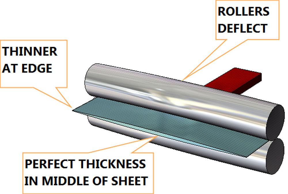
The raw sheet stock is manufactured by rolling ingot between rollers to squeeze the billet into a ribbon. An early stage of the process is shown in Figure 2a. As the hot ribbon cools, it is fed through finishing rollers to achieve the final gauge thickness. Those finishing rollers deflect somewhat in the process. An exaggerated view of this deflection is shown in Figure 2b. The emerging sheet is often thicker in the middle than it is at the extreme edges of the ribbon.
The rollers used to finish the sheet emboss the surface finish onto the sheet. Typically, the rollers are precision-ground with a smooth finish. The resulting mill-rolled finish in the sheet stock is termed “2B” as a finish designation for stainless. An example drawing note might read, “Material: Stainless Steel Sheet, 16 gauge 304 2B.”
The rolling process also introduces a grain direction in the microstructure of the sheet. This micrograin runs parallel to the edge of the ribbon of sheet metal as it comes out of the roller.
As a third source of “grain” in the material, the rolling mill can sand the surface of the ribbon to give it a cosmetically appealing finish. “Material: Stainless Steel Sheet, Pregrained, 16 Gauge 304 #4 with PVC” is a typical designation for pregrained stainless steel sheet stock. Of course, sanding the workpiece for deburring and cosmetic grain might occur at any stage of fabrication.
Whether prefinished or not, the ribbon of sheet metal is subsequently rolled into coils for rail transport (see Figure 2c). A 25-ton coil requires dedicated machinery for handling and storage. This coiling of the ribbon winds nonuniform stress into the raw material.
In a typical supply chain, a regional depot receives the coils of sheet stock from a rolling mill. This distributing depot uncoils and carefully restresses the raw stock to flatten it. An example leveling line is shown in Figure 2d. A leveling line can be set up to flatten a variety of sheet materials while simultaneously cutting rectangular sheets. Examples are shown in Figure 2e. Such pallets of sheet stock are delivered to the fab shop.
Typical sheet sizes are 48 in. by 120 in. for steel and 48 in. by 144 in. for aluminum. Other sheet sizes are available. It is best to check with the fab shop to see what is available from the raw material depot.
Here’s another DFM tip: Proceed with caution. Flat part tolerances cut by well-maintained lasers or turrets usually repeat within ±0.004 in. However, that is not a practical tolerance callout on drawings for job lot production of bent sheet metal.
To minimize the quality control cost of job shop fabrication, we offer the guideline for tolerances. For bent part fabrication tolerances, start with ±0.006 in. to allow for accuracy of the fabrication equipment and add 5 percent of the thickness for each bend. In the example of a 16-ga. L-bracket with a single bend, that’s ±0.009 in. (0.006 + 0.003). For a U-bracket, where two bends or more are needed, the tolerance for at least one of the legs should be ±0.012 in. with ±0.009 in. as the overall default.
The fab shop staff is sensitive to details about tooling and tooling access, flat layout accuracy, grain direction, alloy, finish, and tolerance. These caring experts may carry a title of journeyman sheet metal mechanic. Well-designed 3-D CAD models and thoughtfully prepared 2-D drawings soothe their sensitivities. “Soothing” is roughly equivalent to “suitable for fabrication with existing tooling.”

Figure 1c
In this overlap corner treatment, an overlap is made to make the short sides longer. This might allow one tooling setup to form four flanges instead of requiring two setups, each bending two flanges. The problem with ripped corners remains, however.
As an alternative to single-purpose stamping tooling, a more versatile process is air bending, a bending method that sometimes approaches the technique of bottom bending with a press brake.
Many precision sheet metal job shops offer reliable and predictable air bending as a service. When set up for air bending, the tooling in the press brake does not coin or thin the workpiece as illustrated in Figure 3. As one of life’s miracles, entry-level mainstream 3-D CAD tools have been perfected to predict sheet metal behavior as long as the workpiece doesn’t get coined. That means it works with folding brakes as well as it does with air bending press brakes.
The rolled and then coiled and decoiled raw sheet stress-relieves as it is subsequently cut and bent into a useful item. While some stress runs parallel to the sheet length, not all stress in the flat material is uniform.
Here is a DFM tip: ±1/4 degree on bend angles is “precision” because of the variation in raw material thickness, built-in stress in the workpiece, and variation in the brake’s operation.
The raw sheet has a natural micrograin direction that runs parallel to the 144-in. sheet length. This micrograin impacts the design in terms of strength and appearance.
Bends that run perpendicular to the material’s natural grain require slightly more pressure than those running parallel to the grain. The raw stock tends to crack and fatigue parallel to the micrograin, just as a sheet of wood would.
When sheet stock is bent at close to the fatigue point of the workpiece—where it permanently retains shape without cracking—two closely related characteristics of the material come into play: the micrograin direction and the surface condition of the workpiece.
Surface scratches in the workpiece make it more susceptible to cracking. As mentioned earlier, bends that run parallel to the micrograin will fracture more easily than those that run perpendicular to the grain.
Here’s a DFM tip: When specifying a grain direction, perpendicular to the bend is structurally the best practice.
When wide-belt sanding the flat aluminum workpiece for deburring and a beautiful finish prior to forming, the fab shop makes an effort to avoid cross-graining. In other words, this means running the sandpaper perpendicular to the micrograin inside the sheet stock.

Figure 1d
Bend relief cutouts in the overlapped corner remove the material that will rip or tear. The use of radius instead of sharp corner cutouts reduces the propagation of microfractures in the material. This is good practice for parts subject to vibration.
The surface of cross-grained aluminum may look beautiful before plating, as no trace of cross-grain can be seen, but this kind of beauty is only skin deep. Chemical etching that takes place during the anodizing process reveals a warp-and-woof pattern in the surface that is usually described as unattractive.
Here’s a DFM tip: The grain direction, particularly for anodized parts, can contribute significantly to the raw material utilization and cost for the workpiece.
In the CAD shop, the Base Flange (as designated in most 3-D CAD modeling packages) makes the automatic flat layout possible. The equivalent in the fab shop is a sheet of raw material with relatively uniform thickness. In the CAD shop, a part must have absolutely uniform thickness for the automatic flat layout tools to work.
When association between the fabrication process and CAD matters, the best place to start in a sheet metal design is with the Base Flange. Happily, perhaps, the Convert to Sheet Metal tool allows the CAD jockey to employ any starting feature for modeling design intent or inspiration and end up with a Base Flange.
Here is a DFM tip: When setting up the Base Flange, specify a thickness that corresponds to standard gauge thickness. Typing in the decimal thickness is as easy as entering a dimension value. Fortunately, the Base Flange can be linked to a Gauge Table (see Figure 4). The Gauge Table creates a convenient drop-down list so that only valid sheet metal thicknesses may be selected.
Here is another DFM tip: Use Gauge Tables in your 3-D sheet metal work flow. An accurate Gauge Table helps with modeling speed and provides a degree of self-explanation to other CAD jockeys who review the model. The CAD Gauge Table goof-proofs the selection of bend radii and K-factors.
For this to work, some CAD setup is required. Synchronize the Gauge Table spreadsheet with the fab shop’s Bend Deduction Tables and tooling charts. As a result of using the fab shop’s layout calculations, the flat layouts generated from the design will be 100 percent ready for nesting and fabrication.
In the next episode, we gooseneck at brakes and present specific design guides for bent sheet metal.
Gerald Davis uses CAD software to design and develop products for his clients at www.glddesigns.com. From 1984 to 2004 he owned and operated a job shop. Please send your questions and comments to dand@thefabricator.com.


The Fabricator is North America's leading magazine for the metal forming and fabricating industry. The magazine delivers the news, technical articles, and case histories that enable fabricators to do their jobs more efficiently. The Fabricator has served the industry since 1970.
start your free subscription
Easily access valuable industry resources now with full access to the digital edition of The Fabricator.

Easily access valuable industry resources now with full access to the digital edition of The Welder.

Easily access valuable industry resources now with full access to the digital edition of The Tube and Pipe Journal.

Easily access valuable industry resources now with full access to the digital edition of The Fabricator en Español.
Seth Feldman of Iowa-based Wertzbaugher Services joins The Fabricator Podcast to offer his take as a Gen Zer...


