


Inspecting and verifying fillet weld size
How one company developed a tool for actual variable readings
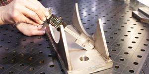
Figure 1When touching the face of the weld, the digital scale reveals the actual distance from the root of the weld to the face, which is the actual weld throat length.
Woolf Aircraft Products Inc., Romulus, Mich., has been fabricating tubular assemblies since 1942. With a 100,000-square-foot facility and 125 employees, we bend tubing from 0.125 inch through 7 in. in diameter with a selection of more than 450 radius dies. Commonly fabricated materials include stainless steel, INCONEL® alloy, carbon steel, chrome-moly, aluminum, and titanium, as well as magnesium, HASTELLOY® X, AL-6XN®, and other exotic alloys.
The Challenge
Many of the weld sizes that we must produce are less than 0.125 in., with some as small as 0.040 in. Inspecting and verifying the sizes of these welds with a traditional fillet weld gauge does not work well, and the custom gauges we've ordered have been so small that they are difficult to use.
In addition, when doing dimensional inspection reports, we have had difficulty obtaining actual readings. Most gauges that are used to measure welds are attribute (go/no go) by nature, which means that they make a comparison only to a template. Some gauges provide a measurement against an imprinted scale to give an estimate of the size, but these gauges are not calibrated and do not offer a variable reading that is traceable to the National Institute of Standards and Technology (NIST)—a requirement of our ISO 9001:2000 and AS9100B registrations.
Another reason we wanted to obtain variable readings was so we could get an actual value of measurement, which would provide us with a precise determination of the actual characteristics of the fillet weld. We work with various welding specifications relating to the inspection of welds. A specific size might be called out, along with a specification that defines the acceptable attributes—weld size, convexity, and concavity –of the fillet weld. We needed to be able to verify those weld attributes with accuracy.
The Solution
The challenge for our company to solve this problem was fostered in the fabrication cell where certain customer projects are handled. Representatives from administration, engineering, and the shop floor worked together to develop a solution.
We started by breaking down the issue at hand. It actually was a very easy problem to solve once we looked at it as an inspection issue rather than a welding issue. The inspection aspect was that we had to be able to measure the leg of a 45-degree triangle and obtain an actual reading. For that reason, we decided to use digital calipers. They have a stem that can be used to measure depth, and the digital scale can be set to zero anywhere along the scale.
The next thing we had to do was to grind a 45-degree point on the stem, as well as 45-degree angles on the ends of the calipers. This allows us to seat the tip of the stem into the root of a 90-degree angle. We made an adapter to provide more surface area for larger parts.
After we finished the prototype, we made a video and sent it to several people for review and suggestions—more so, really, to challenge the validity of the application. We received positive feedback from everyone we sent it to, from customers to AWS officials to local college and vocational authorities.
How the Tool Works
In the end, we had developed an inspection tool that we can use to measure a leg length, as well as the actual weld throat. Using these two known measurements, we can determine the actual size and the convexity and concavity of a fillet weld.
We have made an adapter to mount to a digital caliper that has been designed to seat directly into the corner of a 90-degree angle. The digital scale then is set to zero and used in the same manner against the fillet weld. When touching the face of the weld, the digital scale reveals the actual distance from the root (corner) of the weld to the face, which is the actual weld throat length (see Figure 1).
Using a similar technique to measure the length of a leg, we can determine the individual leg lengths. We use a traditional caliper for this measurement (see Figure 2).
Once we know the two variables of actual throat length and leg length, we can make many determinations regarding the weld size (see Figure 3). The system lets us calculate the theoretical throat length, convexity, and concavity.
This system provides variable measurements that are traceable to NIST and that meet the expectations of the various quality systems. There is no need for cutting and etching to obtain the measurements; we can make determinations without destroying the product and make them as many times on as many welds or parts as necessary.
About the Author
About the Publication
subscribe now

The Fabricator is North America's leading magazine for the metal forming and fabricating industry. The magazine delivers the news, technical articles, and case histories that enable fabricators to do their jobs more efficiently. The Fabricator has served the industry since 1970.
start your free subscription- Stay connected from anywhere

Easily access valuable industry resources now with full access to the digital edition of The Fabricator.

Easily access valuable industry resources now with full access to the digital edition of The Welder.

Easily access valuable industry resources now with full access to the digital edition of The Tube and Pipe Journal.

Easily access valuable industry resources now with full access to the digital edition of The Fabricator en Español.
- Podcasting

In this episode of The Fabricator Podcast, Caleb Chamberlain, co-founder and CEO of OSH Cut, discusses his company’s...
- Trending Articles
1
Tips for creating sheet metal tubes with perforations

2
Are two heads better than one in fiber laser cutting?

3
Supporting the metal fabricating industry through FMA

4
JM Steel triples capacity for solar energy projects at Pennsylvania facility

5
Omco Solar opens second Alabama manufacturing facility
