


When is it acceptable to use limit tolerancing instead of GD&T?
ASME Y14.5 allows for plus/minus tolerances on features of size

Calipers can be used for more than just measuring size. Martin Barraud/iStock/Getty Images Plus
Geometric dimensioning and tolerancing (GD&T) is an effective method for describing the features of a manufactured part with regard to form, location, orientation, and profile. Using basic dimensions and referencing those dimensions to datums established from specifically designated datum features, designers can define some very sophisticated parts, like automotive body panels.
Given the effectiveness of GD&T, is there ever a time to use limit tolerancing instead? ASME Y14.5, Dimensioning and Tolerancing, includes this guidance in its foreword:
“Since many major industries are becoming more global, resulting in the decentralization of design and manufacturing, it is even more important that the design more precisely state the functional requirements. To accomplish this it is becoming increasingly important that the use of geometric and dimensioning (GD&T) replace the former limit dimensioning for form, orientation, location, and profile of part features. This revision contains paragraphs that give a stronger admonition than in the past that the fully defined drawing should be dimensioned using GD&T, with limit dimensioning reserved primarily for the size dimensions for features of size.”
So, what is a feature of size, and what makes it so special?
ASME Y14.5 defines a feature of size as “a single cylindrical or spherical surface or a pair of opposed points, line elements, or surfaces associated with a size dimension.” The keys to this definition are:
- Features of size are characterized by a single measurement.
- The direction of the measurement is defined unambiguously by the feature geometry.
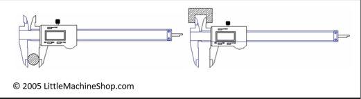
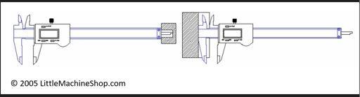
Features of size are what you measure with calipers (see Figure 1). Most calipers measure depth and step (see Figure 2) (as well as ODs, IDs, width, and thickness), but these measurements miss the definition of features of size, because they aren’t formed by “opposing surfaces;” both surfaces “point” in the same direction. Conveniently, depth and step fit into the gray area left in the Y14.5 admonition that limit dimensioning be “reserved primarily for the size dimensions for features of size.”
About the Author
About the Publication

subscribe now

The Fabricator is North America's leading magazine for the metal forming and fabricating industry. The magazine delivers the news, technical articles, and case histories that enable fabricators to do their jobs more efficiently. The Fabricator has served the industry since 1970.
start your free subscription- Stay connected from anywhere

Easily access valuable industry resources now with full access to the digital edition of The Fabricator.

Easily access valuable industry resources now with full access to the digital edition of The Welder.

Easily access valuable industry resources now with full access to the digital edition of The Tube and Pipe Journal.

Easily access valuable industry resources now with full access to the digital edition of The Fabricator en Español.
- Podcasting

In this episode of The Fabricator Podcast, Caleb Chamberlain, co-founder and CEO of OSH Cut, discusses his company’s...
- Trending Articles
1
Tips for creating sheet metal tubes with perforations

2
JM Steel triples capacity for solar energy projects at Pennsylvania facility

3
Are two heads better than one in fiber laser cutting?

4
Supporting the metal fabricating industry through FMA

5
Omco Solar opens second Alabama manufacturing facility
