


Why datums used in CAD should remain distinct from GD&T datum features
How these items are related and what they mean to meeting high-tolerance job specifications

jauhari1/iStock/Getty Images Plus
Editor’s Note: The previous episode of the GD&T Connection was about capturing the designer’s purest intent using basic dimensions and how that relates to plus-or-minus dimensioning methods. This episode begins to explain datum features, datum simulators, and datums.
The symbol used in ASME Y14.5 to designate a datum feature is often referred to as a plunger or a suction cup (see Figure 1). It is stuck on the drawing or model representation of an actual part feature used to establish a datum.
In geometric dimensioning and tolerancing (GD&T), a datum is established when a datum feature meets a datum simulator.
As an example, to design the bracket in Figure 2A, the designer likely would sketch the perimeter on an arbitrary plane and use the edges as references or “implied datums” to locate the holes and slot as quickly as possible—hasty drafting. What’s missing is that this bracket is located in its next assembly by the small hole and the slot. The designer is the first person who knows this, and it might be very useful information to the fabricator, the assembler, and the inspector, both before and after assembly.
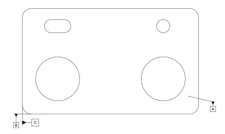
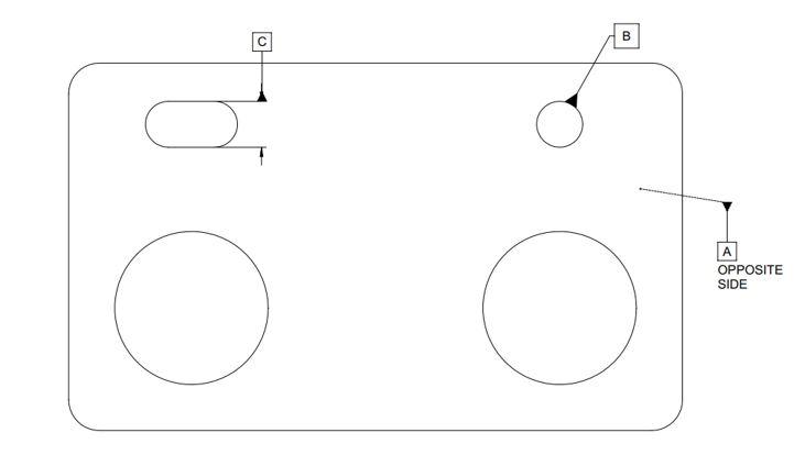
In most cases, leaving the CAD datums as GD&T datums would still be compliant with Y14.5 (see Figure 2B). Doing so, however, will leave off the drawing the useful and potentially cost-saving information of how the part actually locates in assembly (see Figure 2C). This is a matter of a best practice enabled, but not required, by Y14.5. Company standards, or the enforcement of best practices, become important.
The datums used in CAD should remain distinct from GD&T datum features.
Datums Defined
So, what’s the relationship among datums, datum features, and datum simulators?
According to Y14.5, a datum is “a theoretically exact point, axis, or plane derived from the true geometric counterpart of a specified datum feature. A datum is the origin from which the location or geometric characteristics of features of a part are established.”
So, the datum isn’t on the part; that’s the datum feature. And the datum is the “true geometric counterpart” of the datum feature. The datums establish the coordinate system and origin for location and orientation.
And, as stated previously, the datum isn’t established until the datum feature meets the datum simulator, whether the simulator is a machine table, fence, or backgauge, or three hits (for a plane) from a coordinate measuring machine.
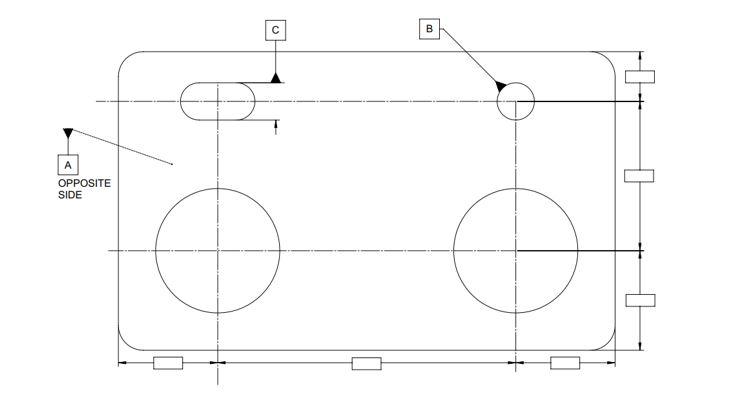
FIGURE 1. Datum feature identifiers can be placed in multiple ways to identify datum features.
Datum Theory Illustrated
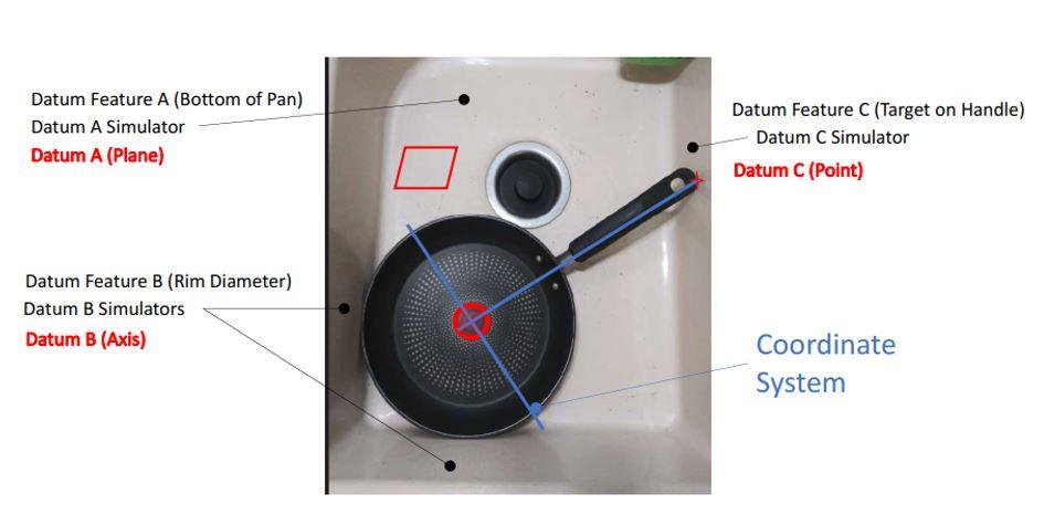
Datum theory is observable at home. Take a frying pan and place it in the kitchen sink. (Assumptions are that the pan is round, the sink is rectangular, and the pan can sit flat on the bottom of the sink.)
The primary datum feature is the bottom of the pan. The datum simulator is the bottom of the sink. The datum is a theoretical plane established between the pan and the sink. The primary datum constrains three degrees of freedom: up/down translation and two up/down rotations. Let’s call this primary datum A.
Now slide the pan into a corner of the sink (see Figure 3). The secondary datum feature is the diameter of the pan’s rim. The side and back wall of the sink are the datum simulators that establish the datum from the datum feature. The datum is the axis of the pan diameter. The axis is perpendicular to the primary datum. The secondary datum constrains the remaining two translations forward/backward and left/right across the bottom of the sink. Let’s call this secondary datum B.
Now rotate the pan until the handle contacts the wall of the sink. The tertiary datum feature is the target area of the handle that touches the wall of the sink (it may be a small target or even a single point). The datum simulator is the wall of the sink that the point on the handle comes into contact with. The datum is one of the two planes perpendicular to each other, through the secondary datum axis, and perpendicular to the primary datum plane. The last degree of freedom to be constrained is rotation around the axis of the pan. You guessed it—tertiary datum C.
With all six degrees of freedom constrained, any point on the surface of the pan and any curve of the surface, inside or out, has specific coordinate locations relative to the datums. This coordinate system often is referred to as the datum reference frame and is specified by the letters in the last set of boxes in a GD&T feature control frame. You also can wash the pan now without its sliding around in the sink.
The origin point of the coordinate system is the intersection of three mutually perpendicular datum planes: the primary bottom of the sink/pan and two planes perpendicular to each other intersecting at the axis of the pan diameter. One of the two vertical planes then is passed through the point of contact between the handle and the sink wall. Note that the planes of the coordinate system need not be (and are not) parallel to, or coincident with, the walls of the sink. They are established from the part datum features.
Mike Matusky is ready to answer your questions and appreciates your comments. Please send your questions and comments to dand@thefabricator.com.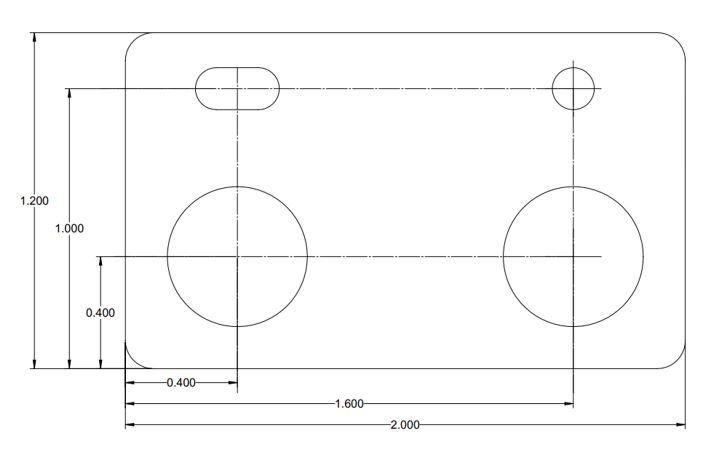
About the Author
About the Publication

subscribe now

The Fabricator is North America's leading magazine for the metal forming and fabricating industry. The magazine delivers the news, technical articles, and case histories that enable fabricators to do their jobs more efficiently. The Fabricator has served the industry since 1970.
start your free subscription- Stay connected from anywhere

Easily access valuable industry resources now with full access to the digital edition of The Fabricator.

Easily access valuable industry resources now with full access to the digital edition of The Welder.

Easily access valuable industry resources now with full access to the digital edition of The Tube and Pipe Journal.

Easily access valuable industry resources now with full access to the digital edition of The Fabricator en Español.
- Podcasting

In this episode of The Fabricator Podcast, Caleb Chamberlain, co-founder and CEO of OSH Cut, discusses his company’s...
- Trending Articles
1
Tips for creating sheet metal tubes with perforations

2
Supporting the metal fabricating industry through FMA

3
JM Steel triples capacity for solar energy projects at Pennsylvania facility

4
Are two heads better than one in fiber laser cutting?

5
Fabricating favorite childhood memories
