


Senior Editor
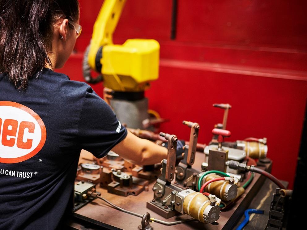
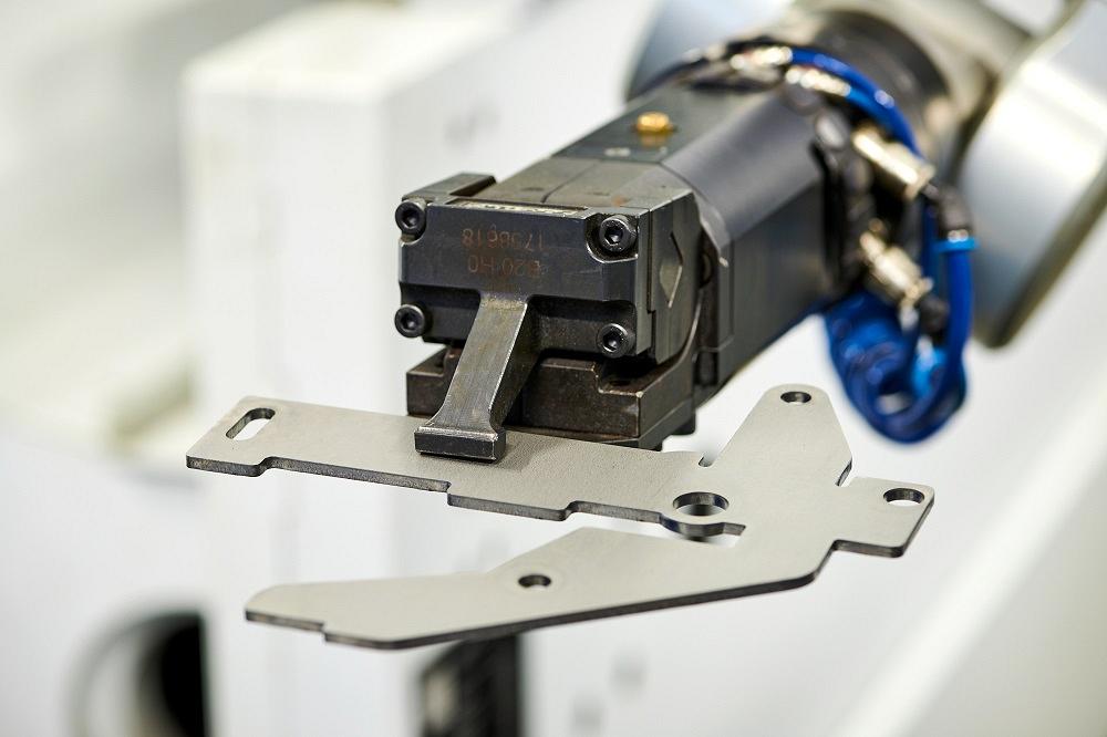
A MEC employee positions a part on a fixturing table with pneumatic clamping. MEC makes use of robotic welding wherever it makes sense to do so. Managers look at myriad factors, including cycle time. On occasion, a mix of automated and manual welding might yield the greatest throughput, despite the extra handling. Images: MEC
In recent months, MEC COO Rand Stille has spent time with the company’s tube fabrication engineers as they work to integrate robotic material handling into the fabricator’s extensive laser tube cutting operations. MEC has been No. 1 on The FABRICATOR’s FAB 40 list for the past dozen years. With more than 2,000 employees and 20 plants, the Mayville, Wis.-based organization pushes the limits of metal fabrication automation. That shouldn’t be a surprise. After all, MEC must have the volume to justify it, right?
That’s only half true. Yes, MEC produces millions of parts, but it also produces a plethora of different part numbers. “For instance, our tube plant [in Neillsville, Wis.] isn’t producing 15 part numbers at a million pieces per part,” Stille said. “It’s just the opposite. We’re producing an incredible variety of part numbers at 15 pieces per run. It’s a high-SKU plant.”
All the same, within the coming months MEC plans to implement some innovative automation that should enhance its tube fabrication capacity. The move points to several trends in how automation is being implemented in metal fabrication overall. First, automation is more about flexibility, less about the volume of a specific part.
Second, quick response matters more than the speed of a particular process, be it cutting, bending, or welding. Speed might enter the equation—for instance, there’s a good reason why MEC has stepped up its investment in 10-kW-and-up laser cutting—but the ability to respond is the deciding factor.
Third, building capacity with redundant, universal capital—which can be adapted to serve a broad product mix—has become even more effective as MEC’s operation has grown. Stille said the approach creates “pressure relief valves” as work is shifted to other plants as needed to better meet customer demand.
MEC manages part flow around changeovers, shortening them and reducing their number as long as the effort doesn’t sacrifice part-flow velocity and build excess work-in-process (WIP). A prime example of this is MEC’s approach to bending automation. Many of MEC’s robotic brakes have staged tooling to produce a variety of jobs, a complicated form in one setup, or a combination of both.
Some parts are bent partially on the robotic brake and then completed manually. That sounds counterintuitive. After all, the strategy adds a processing step. Why not have the brake operator form the complete part?
But as Stille explained, the strategy makes sense when you start scrutinizing the bending cycle times. Say a part has multiple bends at different angles requiring a variety of punches and dies staged across the press brake bed. A robot can bend, say, the first seven bends. But, because of reach or access issues, or because of complications in part gripping, the robot can’t produce the final two forms.
Here is where a closer look at setup and bending cycle time comes into play. Can the robotic system set up the tools quickly? Are the tools common—shared among other jobs in the product mix—or are they unusual or unique? How complex is the bend sequence and part gauging for a robot compared to a person (what’s complex for a robot might not be for a person, and vice versa)? How long is the bending cycle? If the bending cycle is long and the tooling setup strategy makes sense, it still might be reasonable to automate most bending and have the final few bends formed manually.
The same thinking, Stille said, applies to MEC’s approach to welding automation. Many jobs undergo a combination of robotic and manual welding. A job might require manual tacking, or perhaps the weld robot can’t access the last few joints. “There are certain welds that are hard to reach, and a robot can’t do it,” Stille said. “Even so, we’re finding those fewer and farther between thanks to trunnions and other technologies.”
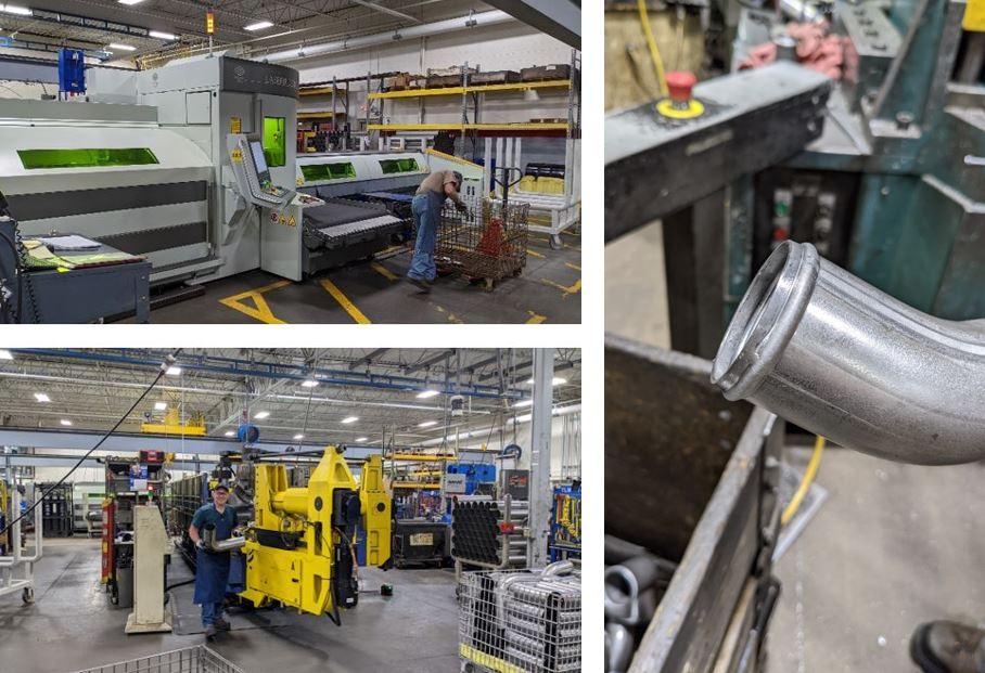
At MEC’s Neillsville, Wis., plant, tube is laser cut, bent, and end formed. In the coming months, the organization will implement a cell that automates the material handling between these and other secondary processes.
Also influencing the automation decision is MEC’s strategy of balancing process cycles in robotic welding. Considering MEC’s high-product-mix environment, a little idle time seems inevitable. Welding requirements can vary greatly even within one subassembly. One piece might require many weld inches while another might call for just a few stitches here and there. In this situation, a typical supervisor or production manager might choose to send those parts with just a few stitch welds to the manual operation.
But at MEC, managers might take a different approach, specifically by balancing the A and B side of the robot cell’s trunnion. “The A side might have a part with a lot of welding on it,” Stille explained. “If you can find enough volume in your portfolio of parts to fill up the B side with several different part numbers, you can balance both sides of the welding cell.”
Such utilization increases throughput in robotic welding, which in turn influences the what-to-automate decision. Yes, robotically welding most of a workpiece only to manually weld the remaining few joints sounds like a classic case of excess handling—but overall throughput still rises.
All this has to be balanced with the resources that automation requires and the cycle time it saves. “The juice has to be worth the squeeze,” Stille said, “and it’s not just about volume. In fact, it’s more about cycle time.”
Stille referred again to the company’s robotic bending. “Say you have a high-volume part with just one simple bend. How much time are you really going to save by automating that?” Automating the part requires at least some programming and a robot gripping strategy. Alternatively, could a manual brake operator do the job faster? “Of course, volume is wonderful [for automation],” Stille said, “but our decision to automate really involves the total cycle time.”
In the coming months, MEC plans to automate material handling between laser tube cutting, bending, and other secondary processes. When looked at through the lens of tube-bending changeover, an automated cell won’t spur significant changes, especially when forming tubes of different diameters. The automated process will have the same changeovers in rotary-draw tube bending as MEC’s current manual process does.
Regardless, all this, Stille said, will be inconsequential compared to the enormous throughput boost. That will come not from an uptick in tube laser cutting or bending speed (the automation will be added to the company’s existing capital) but from eliminating the WIP between several manufacturing steps. The laser will cut the tube, which then will flow immediately to a staging area where a robot will grasp and manipulate it through bending, end forming, and secondary processing. Gone will be all that WIP between cutting and bending. The less WIP a shop carries, the shorter its overall lead time. The shorter MEC’s tube fabrication lead time, the better it can respond to customer demand. Indeed, the technology’s ability to run unattended is just icing on the cake. “We don’t need operators tending to it constantly,” Stille said. “All they need to do is ensure they get a bundle of tube loaded into the tube laser.”
Again, the system won’t be running high volumes. Programming will be set up to handle a variety of work. Once the robot knows the part number, it will call up the program and carry tubes through the necessary operations. Stille conceded that the system will require significant engineering time upfront, but considering the tremendous savings in WIP and increased work velocity, “that upfront work will be well worth the squeeze.”
Blanking, at MEC and elsewhere, acts as a kind of internal supplier, feeding blanks to a variety of value streams. Blanking and its associated automation, both in software and hardware, perform a careful balancing act that produces good material utilization, controls WIP, and encourages robust denesting that presents parts as needed downstream.
In recent years, MEC has increased investment in high-power fiber laser cutting. “We have 10- and 12-kW fiber lasers in four different facilities, and we have multiple high-power machines in each,” Stille said, adding that such increased blanking capacity has served a principal role in “creating those pressure relief valves.” If demand at one plant rises beyond a certain level, Stille and his team can shift work to another plant with spare capacity.
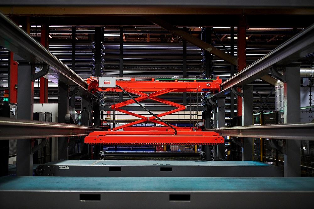
At MEC’s Hazel Park, Mich., facility, a manipulator (in red) places blanks on one of two conveyors that shuttle cut parts to an offload area.
All that cutting power gives MEC the flexibility it needs to deal with highly variable customer demand, a new reality everyone in the industry has faced since 2020. But even before the pandemic, successful contract metal fabricators, MEC included, have built businesses on their ability to adapt. The better and faster they can adapt, the better they serve their customers—hence the push toward high-powered laser cutting.
That said, measuring laser cutting capacity includes more than laser power and measuring cutting speed. Blanking really isn’t “complete” until parts are ready to be processed downstream. Sure, a cut sheet with parts tabbed in place can be shuttled back into a tower, but someone still needs to denest those parts and, if necessary, debur and remove the microtabs. Those cut parts aren’t ready for the next major manufacturing step, so in reality, the blanking process isn’t complete just yet.
Volume of a particular job really doesn’t enter the blanking automation equation. MEC has plenty of multitower laser cutting centers that spend a good portion of the day running an array of low-volume jobs. “With the nesting tools that are available today,” Stille said, “you can cut a plethora of small-volume jobs as long as you put them on the same grade, gauge, and sheet size. You really don’t need to worry about a certain part being a low runner.”
When it comes to nesting and material utilization, the benefits behind MEC’s sheer number of orders really shine. Nesting software has no shortage of jobs to choose from as it looks ahead into the schedule. It’s looking for parts to nest on specific grades, thicknesses, and sheet sizes, all while incorporating the usual factors for laser cutting stability and quality—grain constraints for cosmetics or forming requirements, part orientation (across versus parallel to the slats), and microtabbing for parts stability. Error-proofing also factors in. For instance, if two different parts look similar and could cause confusion downstream, programmers might place those pieces on different nests.
They also consider the labor content of that nest, especially for denesting—a factor that has grown more critical as lasers have gotten faster. All this is made especially evident by MEC’s recent blanking investments, specifically a dual-conveyor system that shuttles blanks to offloading stations.
“It’s typical to have one conveyor per fiber laser,” Stille said. “The conveyor transports material to an operator who removes parts from the skeleton. However, if you get too backed up [in denesting], the machine has to slow down.”
Strategic programming can prevent some of this. A high-powered fiber laser can cut a thin sheet with just a few large blanks in no time flat. That’s great, but sequencing several large-part nests behind a nest full of small parts (which takes longer to cut and especially denest) can lead to a bottleneck at the offloading station. “We balance out small parts and large parts so we aren’t extremely labor intensive on one sheet,” Stille said.
The dual-conveyor system gives MEC another tool to boost blanking throughput. If the primary conveyor is overloaded, the system sends cut parts down a secondary conveyor to a separate area. “We sometimes use that as an overflow area,” Stille said. “The operator removes parts in sequence and then moves to the second offloading table.”
Depending on the schedule and cutting load, water spiders (those who move where needed to relieve a constraint) can help. In many cases, the load reaching a certain level triggers a signal for water spiders to help denest and keep blanks flowing downstream.
Driving MEC’s technology investment, Stille said, is the concept of universal capital: software and machines that can be redeployed quickly to fabricate MEC’s entire product range. The company still works to connect processes whenever it can, the laser tube cutting and bending cell being a prime example. It even designs entire facility layouts around product families. Still, no matter how customized and automated the production floor, MEC uses universal capital as the building blocks.
Responding better to the ebbs and flow of demand is a never-ending quest at the heart of the contract metal fabrication business model. That’s just as true for the 20-person job shop as it is for the 2,000-employee MEC—and these days, both make the journey with automation.


The Fabricator is North America's leading magazine for the metal forming and fabricating industry. The magazine delivers the news, technical articles, and case histories that enable fabricators to do their jobs more efficiently. The Fabricator has served the industry since 1970.
start your free subscription
Easily access valuable industry resources now with full access to the digital edition of The Fabricator.

Easily access valuable industry resources now with full access to the digital edition of The Welder.

Easily access valuable industry resources now with full access to the digital edition of The Tube and Pipe Journal.

Easily access valuable industry resources now with full access to the digital edition of The Fabricator en Español.
In this episode of The Fabricator Podcast, Caleb Chamberlain, co-founder and CEO of OSH Cut, discusses his company’s...


