


Applications Manager
 |
Hydroformed and rectangular cross-section tubes have become popular for new truck and sport utility vehicle (SUV) frames, engine cradles, roof pillars, and suspension members. The ability to achieve high stiffness, exotic shapes, and minimal weight from these structures could drive their applications to even more platforms.
For the manufacturer, the challenge is in cutting these closed tubes with only single-sided access. In the past, the members were produced from folded and spot-welded assemblies that could be punched easily with conventional tooling as flat sheet before forming. Laser robotic cutting cells with fiber-delivered laser beams have been helpful in this area, and end users also are looking to laser robot systems for option holes, short-run production, and prototype systems in sheet metal parts.
The laser source is controlled by the robot or cell controller and is located near the robotic cutting safety enclosure or sometimes above it on a mezzanine to save floor space. Continuous wave (CW) Nd:YAG solid-state lasers at 1.06 micrometers (µm) are used for their fast cutting speeds and fiber-optic capability. Fiber optics with typical lengths of 10 to 30 meters carry the laser energy to the workpiece.
Metal reinforcement in the fiber conduit gives the fiber cables extreme toughness and protection similar to any other conduit in a production cell.
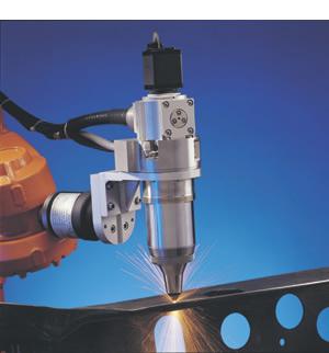
The only real limitation to this delivery is a minimum bend radius of about 200 millimeters. At the end of the robot arm and the termination of the fiber-optic cable is the laser cutting end effector for focusing the laser beam onto the workpiece, maintaining focus on the surface, and delivering the gas jet to aid cutting.
In laser systems that cut flat sheet, the end effector can be rather large, though it must be robust and easy to use. Robotic systems change this concept drastically. The end effector must be designed to be lightweight and small, especially near the cutting tip so it can get close to other features and tooling without interference. It must integrate almost seamlessly with any robot control system for ease of programming. And most of all, it must be well-sealed from dust and vapors, be able to avoid crash conditions whenever possible, and be unharmed by crashes from any direction that will occur.
 |
| Figure 1: The cutting head must follow the surface of the part to keep the laser in focus and to compensate for part-to-part variations. |
To keep the laser in focus on the surface of the part, the end effector uses a capacitive height sensor at the tip of the cutting head that sends commands to a servo system that moves the focus lens and tip to follow the part at about 1 millimeter above the surface (see Figure 1). Travel on these focus-following systems typically is 25 millimeters with a midtravel position feature for teaching the robot path.
A hydroformed tube system with several feature cuts on each of its sidewalls and a feature cut at the end of the tube, called an end cut, can be used in an example of work flow. The first step is hydroforming the tube to the desired shape. After the hydroforming process, the tube should be staged into the laser robot while being held vertically to drain any pooled fluid out of the tube. Fluids can inhibit the laser end effector's surface-following sensors. A dry tube is best, but wet surfaces are acceptable if there is no pooled fluid near the cuts.
 |
| Figure 2 |
The tube then is loaded into a fixture for laser processing--typically a dual rotary system on a trunnion platform. This double-Ferris wheel system allows one tube to be rotated under robot control inside the laser robot enclosure while another tube is loaded outside. Rotating the tube to present each side to the laser end effector minimizes the robot work envelope and air time and allows for the simplest and sturdiest cable routing (see Figure 2). Robot control of the rotary is critical for high-speed, high-quality end cuts without excessive robot contortions.
During laser cutting, the tube ends should be evacuated by an exhaust system to pull the metal vapors and particles out of the cell. When the cutting is complete, the tube should once again be held vertically to remove all slugs. Slugs that drop during the cutting and final manipulations should be funneled into a scrap collection system.
 |
| Figure 3 |
Kerf width of the laser cut is on the order of 0.2 to 0.6 millimeters, and feature sizes are limited only by the motion system. Cutting speeds are determined by the laser power and kerf width. Figure 3 shows a typical laser cutting rate chart. However, laser cutting speed is not the only cycle time criterion. Robotic systems that must traverse from feature to feature spend a large amount of cycle time moving between features. This often is called air time. Fifty percent or more of total cycle time can be taken up by robot air time when the robot is moving at maximum speed. Therefore, it is important to look at the cost of laser cutting speed and the incremental cycle time improvement it brings when costing and estimating a job.
Speed, cost, and quality are the criteria for determining the optimum laser configuration for hydroformed tube cutting. In general, higher average power and smaller kerf width increase cutting speed. However, a narrow kerf requires a much higher oxygen pressure to produce a clean, fast cut. Lasers that produce a narrow kerf also are much less efficient because their design emphasis is on a laser beam that can be delivered with a small-diameter fiber and focused to a small spot.
Therefore, small-kerf lasers use much more electricity and cooling water than a laser of higher average power and larger kerf, with no real increase in cutting speed. Also, a narrow kerf in thick material results in slugs that do not fall out of the tube easily, which can create quality problems.
Another feature of a favorable laser configuration is its ability to pulse the laser beam at a few hundred hertz and have the pulses produced with higher peak powers than the CW level. This produces faster piercing into the tube; the ability to produce faster, more consistent cuts when working off of normal to the surface; better edge quality when cutting around small radii; and faster cutting in reflective materials such as aluminum and zinc-coated materials.
 |
| Figure 4 |
A good system for cutting 2-millimeter and thicker tubing was found to be a 1,500-watt Nd:YAG average-power system that can pulse with up to 2.25 kilowatts (kW) peak power and employs 400- to 600-µm-diameter fiber delivery with focus spot sizes of 400 to 500 µm (see Figure 4). It requires an oxygen pressure of about 15 pounds per square inch (PSI) for a flow rate of 1.0 cubic feet per minute (CFM), as compared to a 300 µm fiber-based system at 75 PSI and flow rate of 7 CFM. This results in a savings of about $1.50 per hour per laser in oxygen cost alone.
Electrical consumption of the optimum-kerf laser unit also is lower because of the higher efficiency of the laser saving—approximately 20 kilowatt-hours (kWh) per laser, or another $2.00 per hour per machine. Cutting speeds are the same. For a typical 3-millimeter-thick tube, the cutting speed is 5 meters per minute.
Robotic motion and its accuracy, smoothness, and repeatability will determine the cut-feature tolerances for the system. Robots from the 1980s and early 1990s were not capable of free-arm trepanning of smooth, accurate features. For holes and slots, many robots used two-axis trepan heads, driving them separately with the robot controller to produce these higher-tolerance features.
As the robot market has grown, and robots' number-crunching capability increased, many medium-payload robots have become fine free-arm trepanning units with special canned subroutines for circular holes, hex openings, etc.
Trepan end effectors also have improved, with new models capable of a large cutting area from one robot arm position, improving shape quality and shape-to-shape accuracies with less air time. Laser cutting alone has a cutting accuracy of about ±35 µm in material a few millimeters thick. With the robot path included, this accuracy typically is ±250 µm. The robot's point-to-point repeatability will determine the actual feature position--typically about ±75 µm.
The optimum robot will have at least six axes of motion, with the capability of one or more additional axes to rotate the tubes or move along the length of the tube. Payload capacity should be specified to handle the laser end effector and accelerate it accurately to trace small features —usually at least 10 kilograms (kg). Canned subroutines resident in the robot controller, which allow the programmer to specify the shape, size, orientation, and lead-in/lead-out, are very helpful and greatly reduce programming time and changes.
Also, robots' working envelopes can be dimensionally mapped at the factory and then software compensated to keep their motion consistent from unit to unit and to match offline programming systems that must use ideal robots for their calculations. These absolute robots have a nearly perfect tool-center point (TCP). The robots also can be friction-compensated for the payload and specific characteristics of their servo system in all planes and with all axes to make rounder circles at faster speeds.
Without the use of external equipment, the robot can measure its motion path and determine what friction compensation values need to be implemented for each feature for optimal accuracy. With this technique, robots have improved the roundness of holes from ±140 µm to better than ±80 µm for any place in the envelope.
As discussed previously, the end effector should be small, narrow, lightweight, and fast. However, these attributes taken to the extreme produce a device that cannot withstand a harsh cutting environment. Stainless steel construction and sliding seals are critical to lessen wear. Hard metal oxide debris and soot can damage optics and motion systems. Quick-change, prealigned gas nozzles and focusing optics are time-savers.
These new-generation cutting heads avoid crashes whenever possible but still have all the durability needed for occasional and inevitable crashes. Recent technology advancements define crash avoidance conditions and monitor for them with signals from the capacitive height sensor and the position of the head to eliminate physical crashes in the Z axis during teaching and even during processing.
One of the most important features is correct tip-to-part distance during cutting when spatter and plasma come from the cut or other close features in the tube, or when cutting at angles to the surface. The latest generation of end effectors can do this and self-calibrate continuously during the process.
Cable routing also is crucial to uptime and ease of programming. The optical fiber, electrical cable, and assist gas plumbing are routed together to the end effector. It is important to keep these cables together and away from the cutting area to prevent snagging on tooling or kinking during motion. All cabling should come into one side of the end effector.
A right-angle end effector design is best so that the fiber optic can be routed into it along the robot's main arm along with all other cables. This eliminates the fiber loop above the end effector, reduces the flexing of the fiber, and allows more access to the work area by keeping the total end effector stack-up at about 200 millimeters.
Right-angle layout also allows the addition of a closed-circuit television (CCTV) and cross-wire generator system to look through the laser optics and produce an image of the focal position on the monitor. This allows the programmer to follow a scribed or a master part during teaching, which greatly reduces the strain and fatigue of programming. When this feature is combined with the capacitive sensor feedback and a robot that can automatically determine the normal to the workpiece, the result is an easy-to-program system.
The operator sets the end effector to the midpoint of travel, or the teach position. Path programming is accomplished by viewing the image on the CCTV monitor and following the master line or finding the center point of a feature. At each point, the programmer can call for an automatic set of the normal by finding the height of the part surface at several places around the point and then compute the normal to the sensed curvature. The robot will move the end effector to the normal, and that new position is entered as the correct point.
Fiber-delivered lasers and robotic systems for cutting were first used in production in the early 1990s. Both technologies have been improving, with robots becoming faster, more accurate, and easier to program. The lasers now have increased power levels of more than 2 kW, and autofocus end effectors are available to handle these high powers.
By choosing the correct unit for the specific job, consumable costs can be reduced by 15 to 25 percent. The end effector must be strong, have crash avoidance capability, and the ease of cable routing and programming that a right-angle version has to offer.
The robot should be capable of utilizing at least six axes of motion. It needs a payload capacity of at least 10 kg and the ability to use a trepanning addition or free-arm trepanning to cut small features accurately and quickly. True ease of teaching is achieved through automatic surface-normal determination, feature shape subroutines, and full robot control integration with the laser and robotic end effector. This combination will achieve maximum throughput and quality at minimum cost.

The Fabricator is North America's leading magazine for the metal forming and fabricating industry. The magazine delivers the news, technical articles, and case histories that enable fabricators to do their jobs more efficiently. The Fabricator has served the industry since 1970.
start your free subscription
Easily access valuable industry resources now with full access to the digital edition of The Fabricator.

Easily access valuable industry resources now with full access to the digital edition of The Welder.

Easily access valuable industry resources now with full access to the digital edition of The Tube and Pipe Journal.

Easily access valuable industry resources now with full access to the digital edition of The Fabricator en Español.
In this episode of The Fabricator Podcast, Caleb Chamberlain, co-founder and CEO of OSH Cut, discusses his company’s...


