


Contributing Writer
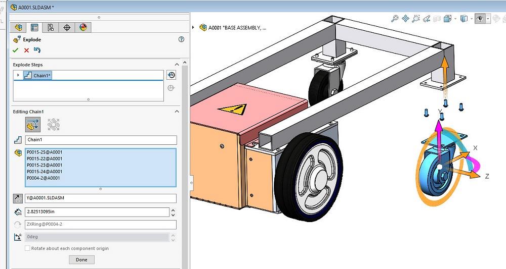
FIGURE 1. An Exploded View that is created with the Auto-Space option turned on will position the parts as the handles are manipulated.
Exploded Views are used to reveal relationships among components in an assembly. There are a variety of methods for manually or automatically separating the components for this purpose, as well as useful tools for adding connecting lines to the view. (Keep in mind that a specific brand of mainstream 3D CAD is being used in this discussion.)
You could create an Exploded View by adding and manipulating mated relationships among components, but that would be tedious. Also, mates are intended for constraining motion, while Exploded Views serve to dispel secrets. The Exploded View tool is oblivious to mates; it positions components for contemplation, not for kinematic study.
An Exploded View’s creation is underway in Figure 1. The Auto-Space Components option is in use. A front caster and its mounting bolts were group-selected with the mouse; handles appeared. One of the handles was then moved with the mouse to position the components as shown.
In this case, the caster was moved a little bit too far down by the Auto-Space drag operation. To edit the result, the caster was individually repositioned to be closer to the bolts with the mouse. With the components positioned in a lovely manner, the next step is to add lines to indicate where the exploded components feel they belong.
As a side note, you could create a 3D sketch and add dashed lines between features on the components. However, the selection of appropriate features in such a process would be tedious. As a convenient alternative to tedium, there is a tool to add connecting lines in an Exploded View.
The tool that adds a single connecting line allows you simply to click on a component to select it, then select the direction for the line, then select the partner component to connect to. You don’t need to fuss with precision clicking.
If a connecting line needs to follow a complex path (pass through a hole along the way, for example), you can select that hole for a connecting line with a simple click. Adding individual connecting lines in this clicky manner provides excellent control over the routing path.
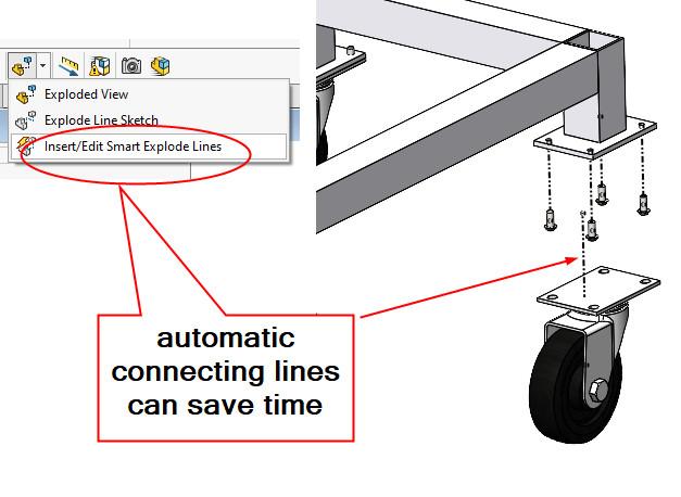
CAD history trivia: About the time of the 2018 release, this brand of software added Smart Exploded Lines. Of course, the legacy exploded lines had their feelings hurt about the other kind of lines being smart, but they persevere. The exploded lines in Figure 2 were inserted as smart ones (in one step) using the indicated menu selection.
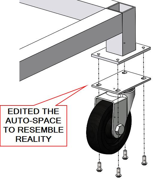
The bolts in Figure 2 are not positioned very well; they seem to have been installed before the caster was. That error was corrected in Figure 3 by simply editing the Exploded View and dragging the caster to be above its bolts.
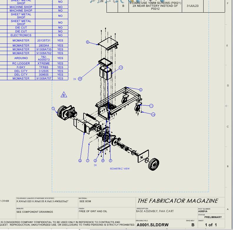
For the cart project, several Exploded Views were created. Figure 4 shows how an Exploded View might be used on a 2D drawing to coordinate with a bill of materials.

The Fabricator is North America's leading magazine for the metal forming and fabricating industry. The magazine delivers the news, technical articles, and case histories that enable fabricators to do their jobs more efficiently. The Fabricator has served the industry since 1970.
start your free subscription


Easily access valuable industry resources now with full access to the digital edition of The Fabricator.

Easily access valuable industry resources now with full access to the digital edition of The Welder.

Easily access valuable industry resources now with full access to the digital edition of The Tube and Pipe Journal.

Easily access valuable industry resources now with full access to the digital edition of The Fabricator en Español.
In this episode of The Fabricator Podcast, Caleb Chamberlain, co-founder and CEO of OSH Cut, discusses his company’s...


