


Owner, Brown Dog Welding

I had never built a “third hand” until this week. I have one in my home shop and use it often, but it is a piece I got from who knows where. For my “day” job at General Dynamics this week, I had to weld a bunch of bosses to a flat plate and decided I needed a little help.
For those who don’t know, a third hand is a thingamabob that fabricators whip up to help stabilize parts they’re welding. I suppose you could get all scientific and mathematical and design one balanced to perfection, but I haven’t found that to be necessary in my day-to-day work. Heck, most of the time I just find a couple of heavy chunks of steel and balance them to hold parts down. The old third hand I have was a bunch of scrap I’m sure an apprentice (maybe even my brother-in-law at Chrysler?) half MIG and half stick welded together. And it’s been fine.
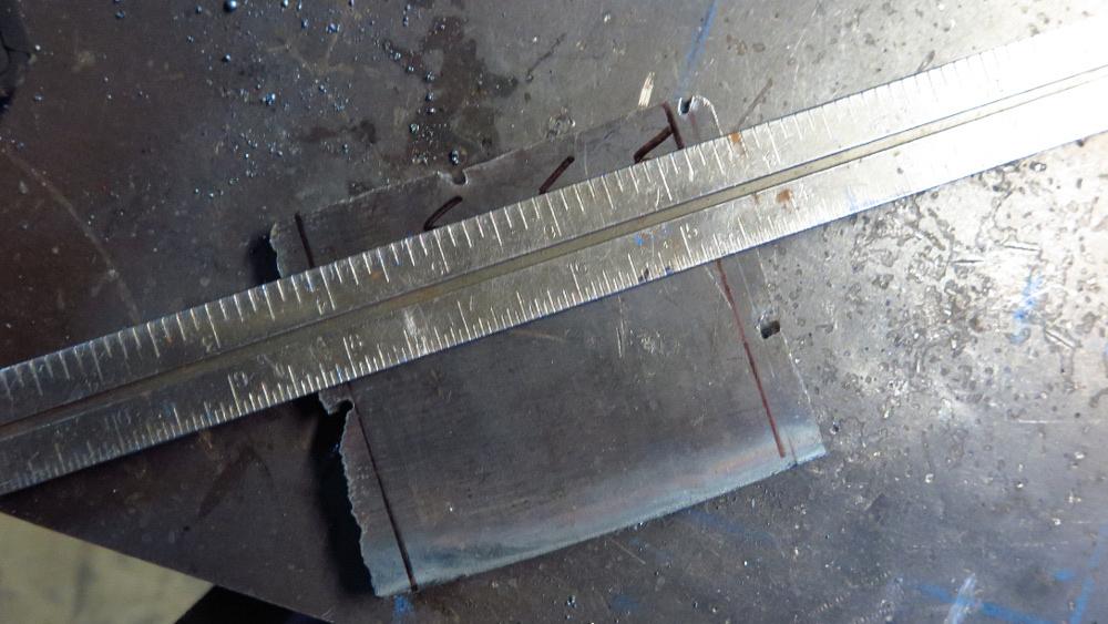
But recently I’ve gotten a few questions about measuring and layout, and while this project would be fine to eyeball, I figured it would be an easy way to show a couple of layout concepts. I found a squarish chunk of steel for the base (Figure 1), part of an axle to make up the body, and an Allen wrench for the holding arm.
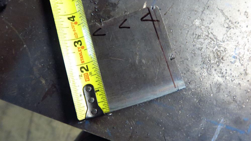
When attempting a layout, the first thing to do is to get a nice edge to work from. I used a straight edge to mark one off, and then I cut it and cleaned it for a nice starting point. From there I used a square to draw two lines relative to the first clean edge, then I used a tape to lay out the third. I marked it off at 3 inches in three places.
When you use a tape or a ruler to mark a measurement, mark it with a V. There will be no confusion as to what spot you intended to call out; it will always be at the point of the V.
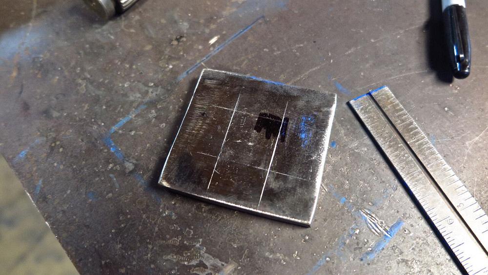
Now, when laying out a line in this matter, always mark it in at least three places (Figure 2). If you do only two, you’d just connect two points and have no clue if one of them is off. If you mark at least three places and put a straight edge through all three (or four, or five) and they all line up (Figure 3), you’re golden. If one or more are off, then you need to double-check your measurements. And if they’re close and your tolerances aren’t tight, you can always just sorta split the difference between the points.
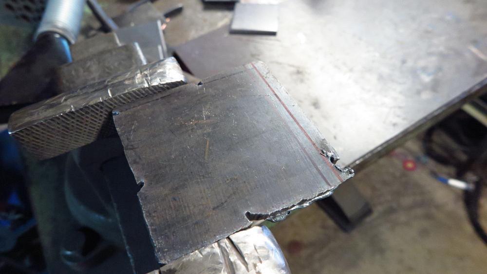
Once the lines were marked, I chopped off the excess metal with a torch and cleaned up the edges with a grinder and flap disc.
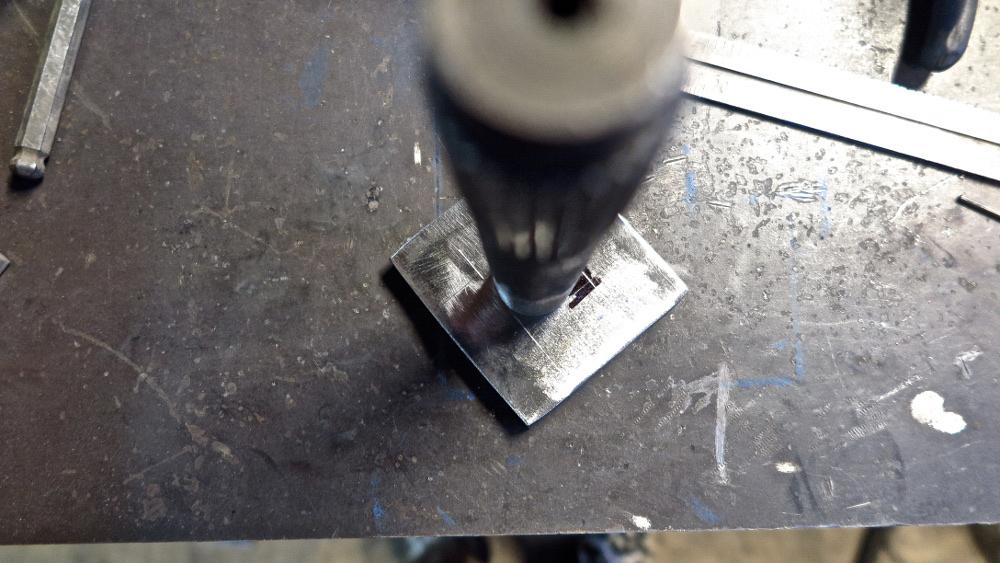
Next, I laid out a box for the axle (Figure 4), which was about 1 1/8 in. in diameter (Figure 5). You want to lay out lines measured from as few lines as possible to eliminate some error if one or more edges is off. If you go off one edge and consistently measure from that one edge, you’ll know at the very least your marks will be good relative to each other.
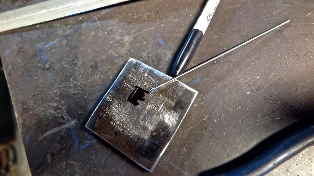
If you need a little help seeing the scribed line and don't have layout dye, a little Sharpie can help (Figure 6). I also often use a sharp tungsten as a scribe.
As I laid out the box, I scribed four lines off two sides. For more complex pieces, it makes sense to work with the least amount of datums necessary.
"Third hand" balancing act.
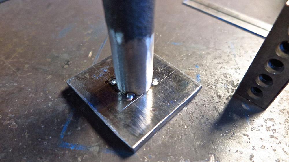
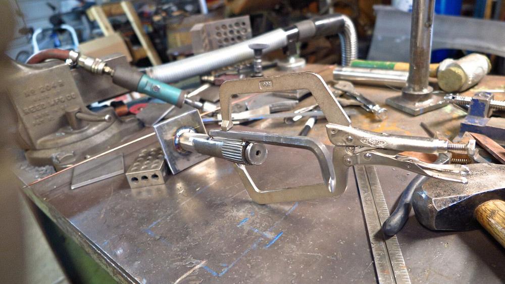
If the box is laid out to a tight tolerance, there should be four tangents where the circle just touches the edge (Figure 7). I like to tack round pieces in quarters(
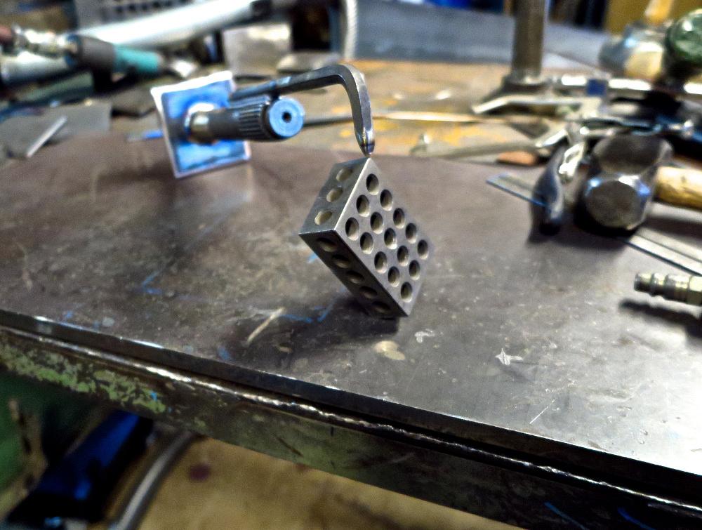
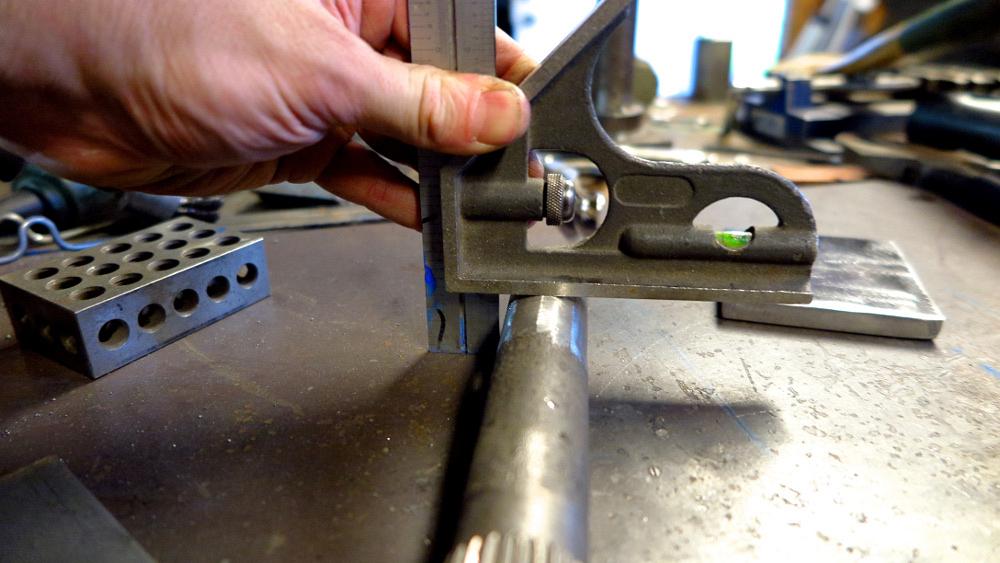
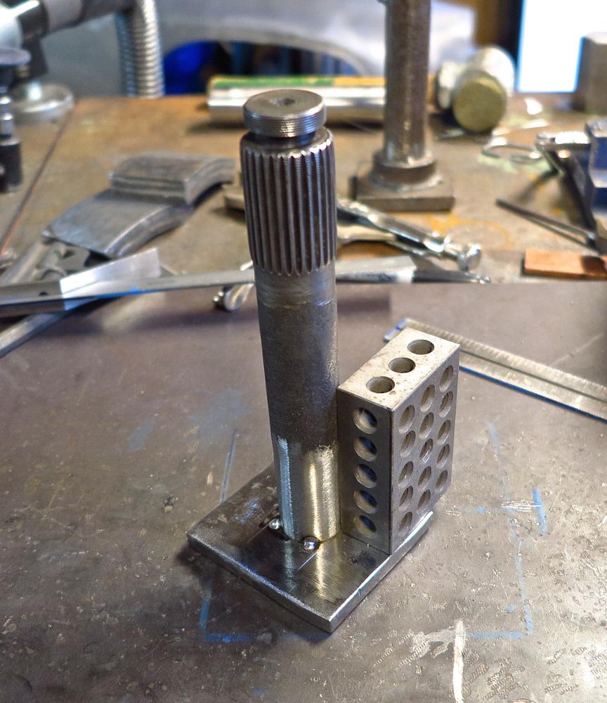
I also tack in the spaces between the tangents; if I have to cut the part or realign it, I might be able to use the same scribed lines. A check for squareness from a machinist’s block (Figure 9) and it’s on to the next step.
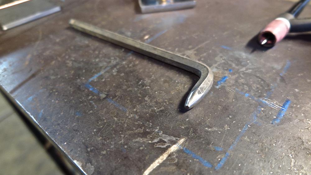
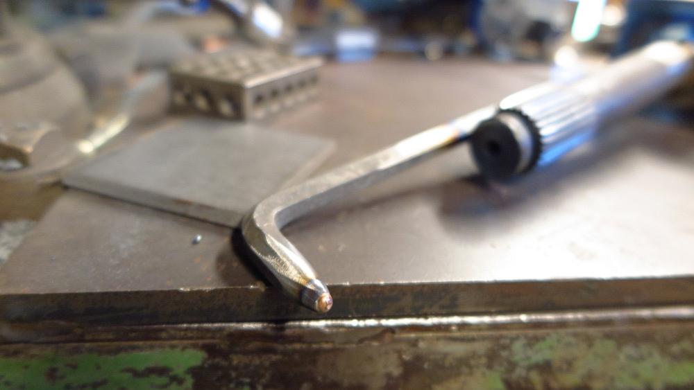
I ground the small end of the wrench’s L leg to a point (
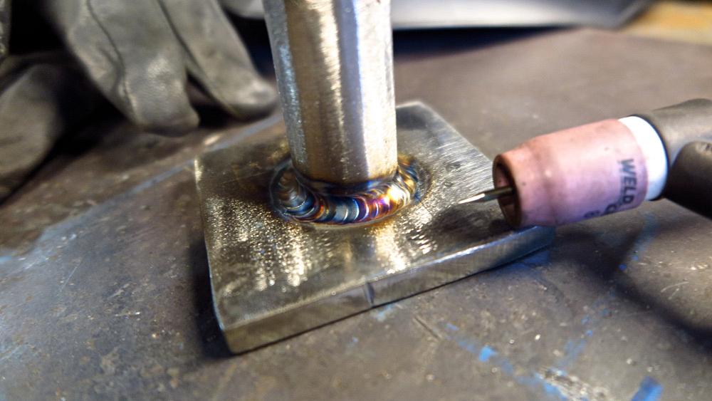
My friend Jody Collier, who has a blog called WeldingTipsandTricks.com, puts a pretty good theory to use on a third hand he built. Occasionally on clean surfaces he’d get an undesirable arc mark from the arc completing through the hand’s metal. Jody figured that bronze is a good conductor, and if he added some to the points on the third hand that made contact with the table and the part, he’d create better conductive points, and the arc wouldn’t wander. He was right. So I added a little silicon bronze to the tip that will hold the part (Figure 12), and I TIG brazed SIB all the way around the base (Figure 13). I should have a good ground when I put this thing to use.
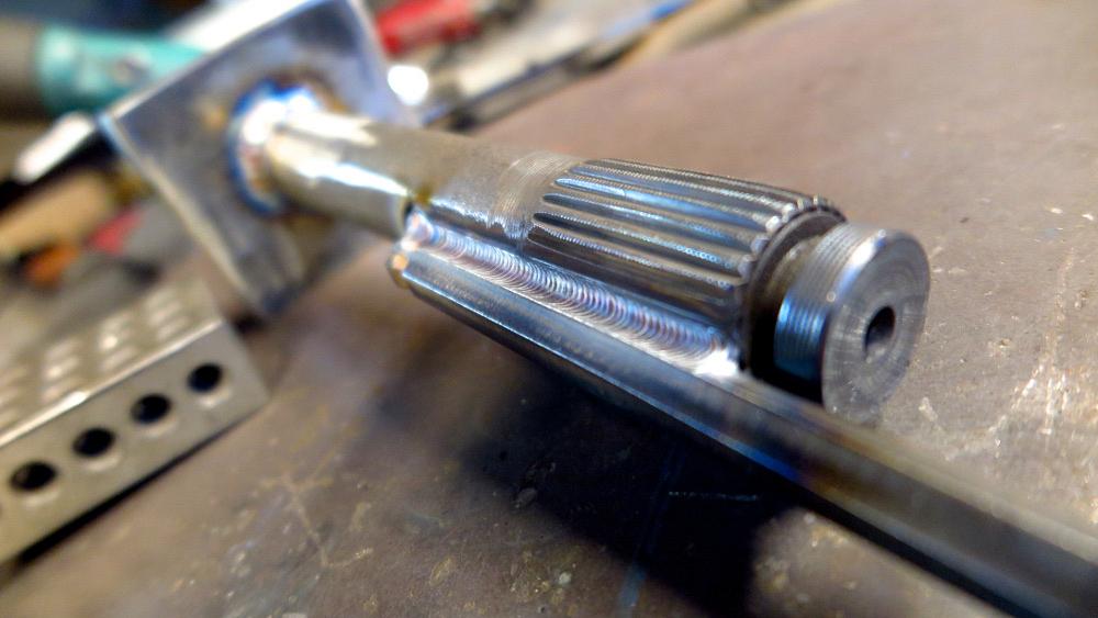
So there it is, completed (Figure 14). The concepts I wrote about in building this are waaaaay overkill for what I made, but they could be helpful to you in other projects.
All photos courtesy of Brown Dog Welding,

The Welder, formerly known as Practical Welding Today, is a showcase of the real people who make the products we use and work with every day. This magazine has served the welding community in North America well for more than 20 years.
start your free subscription

Easily access valuable industry resources now with full access to the digital edition of The Fabricator.

Easily access valuable industry resources now with full access to the digital edition of The Welder.

Easily access valuable industry resources now with full access to the digital edition of The Tube and Pipe Journal.

Easily access valuable industry resources now with full access to the digital edition of The Fabricator en Español.
In this episode of The Fabricator Podcast, Caleb Chamberlain, co-founder and CEO of OSH Cut, discusses his company’s...


