


General Manager
Several types of cutting machines are available for production cutting of tube and bar, such as cold saws, band saws, lasers, shears, waterjets, and abrasive cutting machines. While each has its advantages and disadvantages, abrasive cutting fills a niche with its ability to accommodate special applications, such as difficult-to-cut stock; tube that must be cut cleanly without serious distortion, especially very thin-walled tube; short cut lengths; and applications that require scrap minimization.
A typical automatic abrasive cutting machine anatomy comprises a feeder, a machine vise area with cutting head, an ejection system and collector, and electronics and software that control the system (see Figure 1). At the heart of this system is the cutting component, the abrasive wheel.
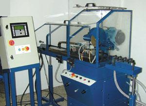 |
| Figure 1 Automatic abrasive cutting machines are enclosed for operator safety. A keypad (at left) allows the operator to program the machine. |
Nonreinforced abrasive wheels—which typically are used in abrasive cutting machines—are made with aluminum oxide, silicon carbide, zirconia, diamond, and cubic boron nitride. Of these, only aluminum oxide and silicon carbide are used for cutting ferrous and nonferrous metals and alloys.
The wheel's aluminum oxide or silicon carbide particles are bonded together with rubber, resin, or a combination of both binders. Rubber-bonded wheels can be produced with a thinner, more uniform thickness than resin-bonded wheels. Rubber-bonded cutting wheels must be used with a coolant and are suitable for production cutting, provided the use of coolant is not a problem.
These wheels rely on the cutting action of the aluminum oxide or silicon carbide particles that break down during cutting, continuously providing fresh cutting surfaces. In this way, the cutting wheel is continuously worn down during the cutting process. Wheel wear therefore is a significant consideration in the design of production machines. Its effects are far-reaching in the economics of using abrasive cutting for production.
The parameters that affect how a cutting wheel performs are:
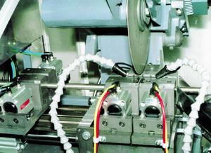 |
| Figure 2 A grip feeder system includes a grip feeder vise that advances material into left- and right-hand machine vises. The cutting wheel is resting just above the vise. |
Guidelines for Use. The following guidelines apply to the use of rubber-bonded and resin-bonded cutting wheels:
Flanges. European and U.S. regulations govern the size of flanges that clamp the cutting wheel. Recessed flanges provide wheel stability and reduce spindle flexing and wear. The Federation of European Producers of Abrasives (FEPA) regulations for using nonreinforced abrasive cutting wheels require a flange size of at least one-third the cutting wheel diameter. U.S. regulations, specifically, American National Standards Institute (ANSI) B7.1, permit the use of flanges that are one-fourth the cutting wheel diameter.
The function of the grip feeder system is to clamp the tube or bar and advance it into the machine’s vises by a preset amount, or cut length (see Figure 2). The grip feeder vise baseplate is mounted on linear bars or guides and is moved either by a pneumatic cylinder or stepper motor-controlled ball screw.
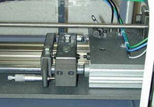 |
| Figure 3 An integral component of a pneumatic grip feeder is an adjustable precision stop. |
The grip feeder vises and the machine vises work in concert. The gripper feeder vises grip and advance the material into the cutting position. Then the machine vises secure the workpiece, and the gripper feeder vises release the workpiece and return to their home position.
In a pneumatic system the grip feeder vise moves along linear bars pushed by a rodless cylinder. The cut length is defined by the position of a precision stop. This position can be displayed digitally to aid setting the stop position (see Figure 3).
Alternatively, when the position of the grip feeder vise is controlled electronically, a stepper motor or servomotor rotates a precision ball screw to position the vise. In this case, data such as length, quantity, and kerf loss can be entered via a keypad or touchscreen (see Figure 1).
The design of machine vises is critical to the performance of the cutting machine (see Figure 2). They perform the following functions:
The right- and left-hand vises have pneumatically operated front jaws. The inner side faces of the jaw have carbide inserts, which guide the cutting wheel to the point of contact with the workpiece. Coolant is sprayed down the wheel slot, and relief grooves in the carbide inserts ensure coolant reaches the cutting area.
Two fiber-optic blocks are fitted on the jaw support in the arc of the cutting wheel. The fiber optics are connected to emitter/detector modules that detect the cutting wheel edge. This is the rest position for the cutting head between cuts.
Each time the grip feeder vise advances the material into the right-hand vise, the previous cut length is pushed out of the vise and ejected down a chute. For very thin-wall or soft tube, modifications to the machine can cushion the fall of the cut pieces.
Electronics and software, which are integral components of modern abrasive saws, allow the operator to set various cutting parameters to enhance cut quality and productivity. In addition to controlling the aforementioned machine functions, they can adjust the wheel speed to compensate for wheel wear.
The importance of wheel wear in the design of production machines cannot be overemphasized. An electronics package monitors the diameter of the wheel as it wears and signals when the wheel has worn to its minimum diameter, which is when the wheel flanges are close to the top of the vise.
A typical system that monitors wheel wear includes:
This electronics package permits setting the minimum wheel diameter that will cut through the material before the cutting head is obstructed. It also allows an operator to vary the depth of cut according to the size of tube or bar being cut.
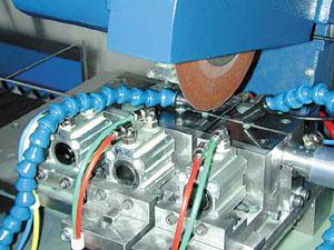 |
| Figure 4 Close-tolerance cutting of short lengths is facilitated with a precision actuator. |
Hand in hand with wheel wear compensation is the need for constant speed at the cutting wheel's periphery (circumference) as it wears down. This provides reproducible cutting conditions, regardless of wheel diameter, and leads to longer wheel life. To maintain constant wheel perimeter speed, an operator programs the wheel speed inverter to speed up as the wheel wears down and its periphery decreases.
The factors that contribute to accurate cut lengths are:
A pneumatic grip feeder system usually is designed to move back and forth between fixed end stops (see Figure 3). Provided care is taken to prevent bounce when the grip feeder vise contacts the end stops, the feeding system does not have a major influence on cut length accuracy. Incorporating stepper-controlled actuators with encoders can significantly enhance system accuracy.
Finally, aligning the cutting head (and cutting wheel) with the wheel slot between the right- and left-hand vises is crucial to achieving a perpendicular, or square, cut.
When these factors are taken into account and the abrasive cutting machine is designed accordingly, tolerances of ±0.002 inch are possible on short cut lengths (3 to 4 in.).
INCONEL and MONEL are registered trademarks of Special Metals Corp. HASTELLOY is a registered trademark of Haynes Intl. Kovar is a registered trademark of CRS Holdings Inc.
Federation of European Producers of Abrasives, 20 Avenue Reille, 75014 Paris, France, phone +33-1-45 81 25 90, fax +33-1-45 81 62 94, e-mail fepa@compuserve.com, Web site www.fepa-abrasives.org.
American National Standards Institute, 1819 L St., N.W., Washington, DC 20036, phone 202-293-8020, fax 202-293-9287, Web site www.ansi.org.

The Tube and Pipe Journal became the first magazine dedicated to serving the metal tube and pipe industry in 1990. Today, it remains the only North American publication devoted to this industry, and it has become the most trusted source of information for tube and pipe professionals.
start your free subscription
Easily access valuable industry resources now with full access to the digital edition of The Fabricator.

Easily access valuable industry resources now with full access to the digital edition of The Welder.

Easily access valuable industry resources now with full access to the digital edition of The Tube and Pipe Journal.

Easily access valuable industry resources now with full access to the digital edition of The Fabricator en Español.
Seth Feldman of Iowa-based Wertzbaugher Services joins The Fabricator Podcast to offer his take as a Gen Zer...


