


Vice President of Sales and Marketing
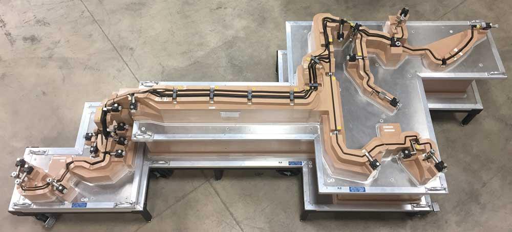
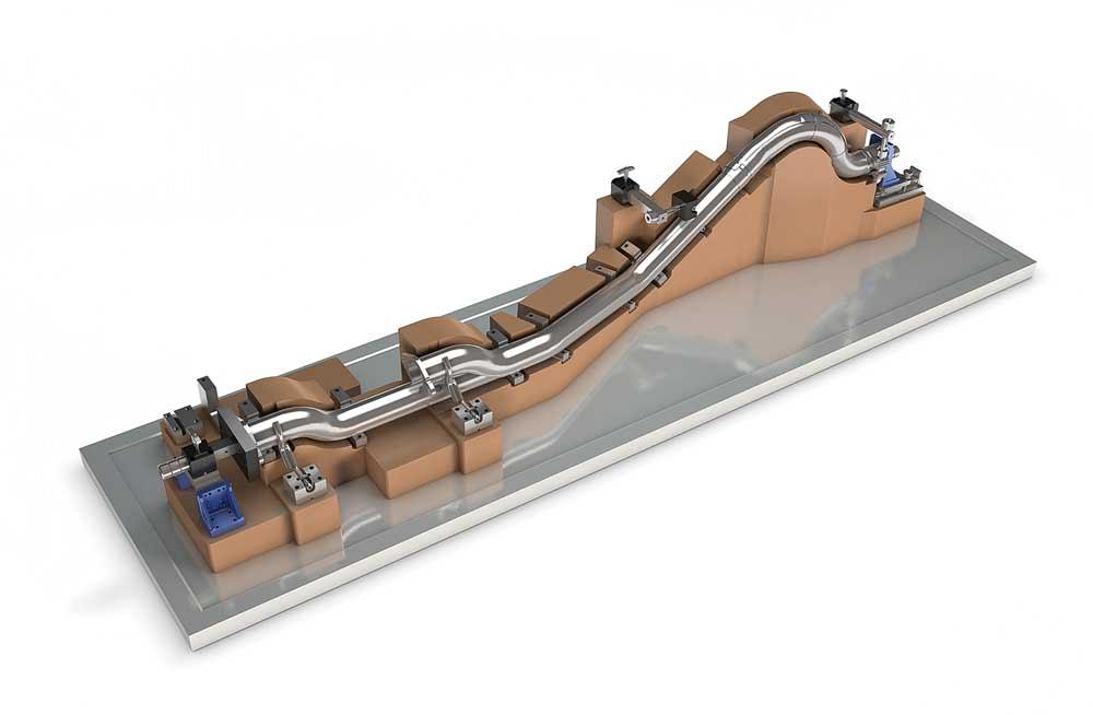
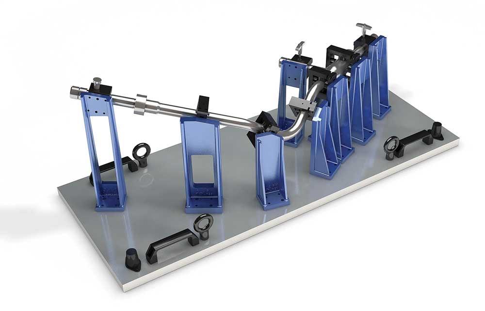
Although many check fixtures verify the dimensions of a single tube just a couple feet long, this versatile concept can be used to verify long assemblies. This fixture provides a quality control check for an assembly of fuel lines and brake lines for an automotive application.
Quality control always has been an integral part of manufacturing, but certainly the earliest standards for quality would pale by today’s standards. Whether using a profilometer to measure a polished component’s surface roughness, a laser-based system to measure a round part’s eccentricity, or a coordinate measuring machine (CMM) to take a series of dimensional readings, modern quality control measurements tend to be an order of magnitude more accurate than those used decades ago.
Micrometers and assorted gauges were once at the cutting edge for making dimensional checks, but these have given way to all manner of specialized tools and processes, providing measurement speeds, levels of precision, and convenience of use unimaginable a few decades ago. As with all tools, they have evolved through stages of sophistication. A modern check fixture—a jig that replicates an installed location for a metal component such as a formed tube—is made from a tough composite material with various sliding features to verify brackets and end-locations. Contrast that with the first check fixtures, made from lengths of two-by-four lumber nailed to 1/2-inch-thick plywood, or cobbled together from lengths of angle iron, and you can see how far this industry has come.
Meanwhile, other tools and systems, such as CMMs, articulating measuring arms, and optical systems have forced the quality verification process to become ever more formalized. Taking a multitude of measurements with a micrometer and annotating the readings with pencil and paper led to sophisticated systems that take far more measurements in far less time and can create a digital record for traceability.
Increasingly sophisticated manufact-uring systems also are driving the industry forward. For example, CNC machine and software have made tube fabrication more precise than ever. As cut lengths become more exact and control systems provide greater accuracy in bent and formed parts, manufacturers increasingly adopt robotic welding technology. Because robotic welding systems aren’t very tolerant of fit-up variances, manufacturing systems that employ robotic welding technologies have to fortify their upstream operations to provide stricter dimensional consistency, creating a cycle of increasingly tight tolerances at each stage of manufacturing.
Dealing with specifications and tolerances sounds simple. A cut is to be made at a precise location so the resulting component has specified length, and the tolerance indicates the absolute shortest and longest lengths that are acceptable. However, while a straightforward specification is easy to understand, in many cases manufactured products are far too complex to be described by just a number or two. When manufactured items incorporate complex shapes, unusual features, and intricate contours, the numbers that describe them become more than mere numbers—they become designations that represent dimensions and feature locations on complex surfaces, giving meaning to points, lines, planes, angles, and curves.
An additional complication is that no single, all-encompassing, universal system is used in industry to define specifications. Is the intersection of two lines a cube or a sphere? Certainly most people don’t realize that it could be one or the other, and it’s likely that most laymen don’t care, but to someone who is measuring or checking a tube assembly, it makes a difference. The program behind a CMM or articulating arm is written from the perspective of the programmer. If a fabricator’s CMM’s software conceives every point in space as a sphere, and if an OEM’s system interprets them as cubes, they generate different measurement results.
As manufacturing tolerances become tighter and industry relies more heavily on geometric dimensioning and tolerancing (GD&T) callouts, disagreements ensue. It’s out of the ordinary, but not out of the question, that a shipment of parts passes a dimensional check before it leaves the supplier’s loading dock and then fails at the customer’s receiving dock. Needless to say, this can become extremely expensive for both parties. One can’t build and sell its products, the other can’t get paid for the work that it did, and neither is in the wrong.
Fulfilling a contract is a matter of fulfilling expectations, so both parties must understand what’s expected. Qualifying a manufactured part doesn’t have to be hopelessly complicated; it’s a matter of understanding that several systems and strategies for qualifying a part exist and that it’s necessary to find one that is mutually agreeable. This agreement must include the type of qualifying instrument and how the instrument itself is to be qualified. Otherwise, conflicts and needless expenses are sure to arise.
Few would assume that what works for tube verification is going to work for a machined engine block. The geometry is different, and the issues are different. Some in the tube bending industry believe their work to be best described as a black art. This is an overstatement, but nonetheless, some aspects and dimensions of bent tube can be difficult to quantify.
In checking tubular components, some fabricators and OEMs rely on CMMs; others use check fixtures. A CMM can be used to check many geometries, while a check fixture is a custom-made fixturing device suitable for checking just one part. The operator places the bent tube or assembly into the fixture, and if it fits into the fixture without force, the part is good. No special training is necessary, and the results don’t vary from operator to operator. When using a CMM and a touch probe, each operator has to take identical measurements from identical locations, which can take a lot of time. Also, if the part isn’t fully clamped or supported, the act of pressing the touch probe against the tube can cause a small amount of deflection, resulting in an inaccurate measurement.
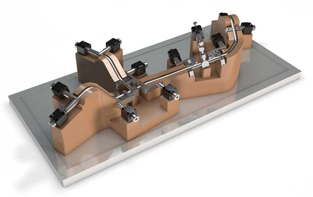
A full-cavity-style check fixture captures the tube on three sides, leaving essentially no room for human error. After placing the tube into the fixture, the operator slides the pins into place and closes the clamps. If the tube fits without force, it meets the dimensional criteria and therefore is ready to go to the production line.
In many cases, fabricators and OEMs use a variety of verification technologies. This makes sense in matters of capability, speed, budget, and operator skill. For example, an OEM might use vision systems at one stage of production and a check fixture at another stage on the same part. It might be a matter of verifying simple subcomponents on the vision system before assembling the subcomponents and checking them on a check fixture. Disregarding the most appropriate use for each technology can result in a perfectly good part passing an inspection by one method and failing an inspection performed by a different method.
Two industries have a predilection for check fixtures: aerospace and automotive. In both cases, accuracy is paramount. Automotive applications have a second motivation, and that’s speed. Using a check fixture usually just takes a few moments, and the operator doesn’t have to annotate anything specific regarding features or dimensions that are out of specification. It’s either go or no go.
What does a check fixture provide? A well-designed check fixture incorporates the requirements as required by the customer in regard to the print, datum scheme, and GD&T. In the automotive and aerospace industries, it’s common practice to indicate that the tube must fit within a toleranced tunnel. Beyond that, various other features on the assembly have GD&T callouts. One end is likely to be the reference datum because it is going to be threaded into some component that is already established in the product’s design. The other end normally has some allowable tolerance at the other end. The check fixture needs to mirror this same approach.
A simplified view, one that usually is inadequate, is to capture the straights and consider this to be sufficient. The check fixture needs to capture the location of every pertinent feature, and often this means a full-capture approach of the complete tube, end to end. This provides the necessary confidence that the part meets the customer’s requirements.
Some fixtures capture the part on two sides only, thereby requiring the operator to verify the tube’s location on a scribe line on the third side. This is acceptable in some situations, but in most cases it’s best to capture the tube on three sides, leaving only the top open to interpretation.
The risk in a two-side capture, leaving more to the discretion of the quality control technician, is misunderstanding how to use the check fixture and discarding good parts.
Bear in mind that fabricators and OEMs also must agree as to how their tools are to be calibrated or certified. Just as the most sophisticated digital instruments need periodic calibration, a check fixture must be certified for accuracy before it is put into use. Progress in this area has been substantial. Twenty-five years ago a signed letter from the company that provided the check fixture might have been considered sufficient. It wasn’t really sufficient then, and it certainly isn’t now. It is critical to use established measurement practices and equipment qualified to a NIST standard. This assures both the fabricator and OEM that the check fixture is an accurate judge of a component’s dimensional integrity.
In today’s environment, we are facing an exciting time. New discoveries are being made, new technologies are being developed, and established techniques are being combined in new ways. A case in point is the use of QR codes, inexpensive hand-held scanners, modern enterprise resource planning software, and Wi-Fi, which contribute to Industry 4.0. The resulting organization on the shop floor means that parts can move through a shop faster than ever before, and if the system has enough sophistication, customers can check on their orders. Technology and customer expectations reduce the time from order to shipment.
At the same time, many OEMs rely on just-in-time deliveries, so they don’t have time to inspect incoming shipments of parts. In some cases, they don’t even unpack the parts—the shipping crate goes straight to the production line.
Therefore, it is imperative that the connection point between the customer and the supplier, which is the delivery, be as uneventful as possible. In a worst-case scenario, that nexus point results in a lost business relationship. In a next-to-worst-case scenario, parts are rejected and profits are erased.

The Tube and Pipe Journal became the first magazine dedicated to serving the metal tube and pipe industry in 1990. Today, it remains the only North American publication devoted to this industry, and it has become the most trusted source of information for tube and pipe professionals.
start your free subscription
Easily access valuable industry resources now with full access to the digital edition of The Fabricator.

Easily access valuable industry resources now with full access to the digital edition of The Welder.

Easily access valuable industry resources now with full access to the digital edition of The Tube and Pipe Journal.

Easily access valuable industry resources now with full access to the digital edition of The Fabricator en Español.
Seth Feldman of Iowa-based Wertzbaugher Services joins The Fabricator Podcast to offer his take as a Gen Zer...


