


Application Engineering Manager
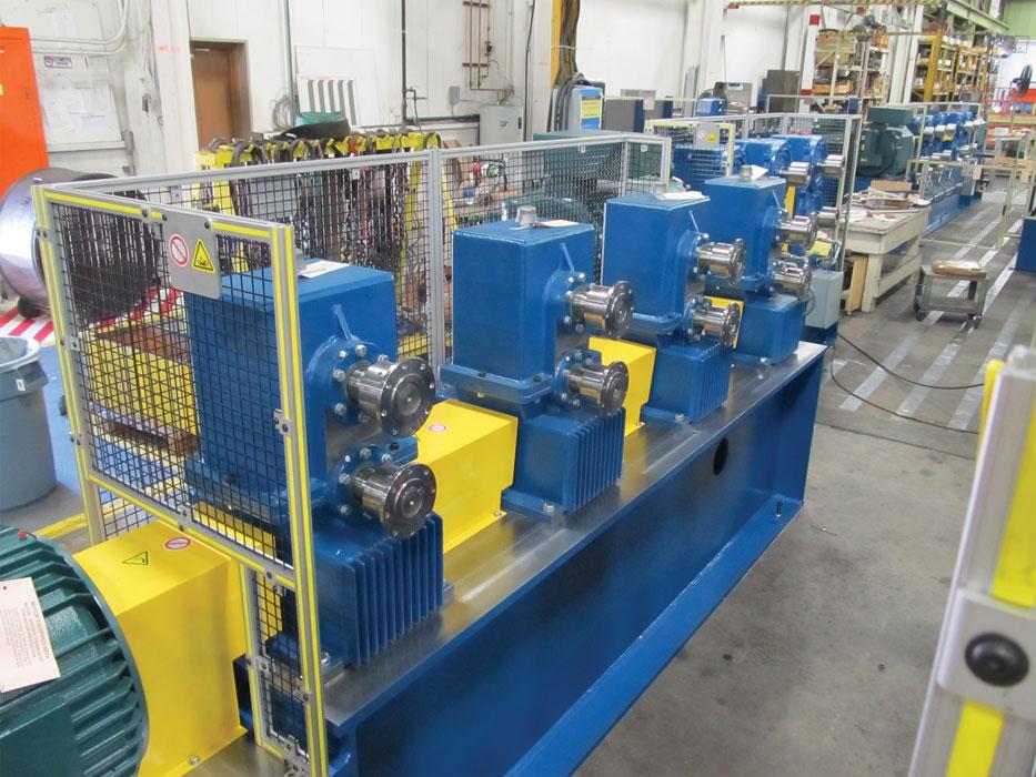
Figure 1
In a typical welded mill, four worm reducers are driven by one AC drive system. Photo courtesy of Formtek Inc. – Yoder.
Although forming tube or pipe on a welding mill seems to be a simple process, the details are complex. One of the complexities has to do with diameter change. A product that leaves the mill measuring 2.375 inches at the outside diameter is formed to a larger diameter at the beginning of the process. Tube and pipe are formed oversized for two reasons. First, the squeeze rolls in the weld box have to exert enough pressure to force impurities and slag out of the weld puddle while it’s red-hot; in doing so, they shrink the diameter. Second, the sizing section has to fine-tune the tube or pipe to its final size, which also reduces the diameter. These two stages of the forming work only when the initial diameter is larger than the final diameter.
Although the diameter changes from entry to exit, the volume of material doesn’t change. This means that, as the diameter decreases, the length increases. In turn, this means that the tooling near the exit end of the mill must rotate at a faster speed than the tooling at the entry end.
However, it’s not quite that simple. Another factor is tension. The roll stands pull the material through the mill, and to form the tube or pipe properly, the tooling has to maintain tension on the tube or pipe. Ideally, the rotational speed of each tooling set is faster still. In other words, if the workpiece’s length increases by 1 percent as it progresses from one stand to the next, the roll tooling speed has to increase more than 1 percent from station to station to keep the workpiece under tension.
Is this the case with every mill? No. For many years, tube and pipe mills have had a Goldilocks problem. As the girl in the fable explores the bears’ home, she finds that one bowl of porridge is too hot, one is too cold, and one is just right; one chair is too big, one is too small, and one is just right; one bed is too hard, one is too soft, and one is just right. The conventional mill drive system is just like that. Some rolls run too fast, some run too slow, and some are just right.
This has to do with the group drive trains used on conventional mills (see Figure 1). A worm gear unit drives a group of shafts, so all of the tools in a particular set—that is, the top and bottom rolls of every stand in a group of stands—rotate at a single speed. This setup reflects the only technology available in previous decades, and while it is capable and robust, it’s not ideal.
Times change, technologies improve, and in the realm of electronic products, costs fall. This process of technological innovation upends traditional notions of how things work. Automobile steering systems went from mechanical (rack-and-pinion or recirculating ball systems) to power steering (either of the aforementioned systems, augmented by a small hydraulic unit) to motor-driven power steering (MDPS, which uses servomotors instead of a hydraulic unit).
Similar innovations have changed the drive systems that are available for weld mills. In addition to a single drive train for a group of stands, another choice is one drive unit per stand (see Figure 2). No longer locked in to a single drive speed for several stands, the mill engineer can use this type of system to trim each stand separately.
Initially this technology was adopted for use in large-diameter pipe mills. The price and availability of many of the large-capacity system components, those needed for such mills, changed over the years. These changes altered the cost-benefit ratios of these systems.
In addition to the capital investment, operational efficiency also is a factor. Worm screw components have a lot of surface area, which means they develop a lot of friction. Depending on the application and the system size, the friction can be a substantial obstacle on the path to operational efficiency. Helical systems are inherently more efficient, which means they deliver a higher portion of the power to the roll stands. On some large-diameter pipe mills, the drive system relies on 1,000-horsepower motors, so converting even a small proportion of formerly wasted power to useful power can add up to significant savings.
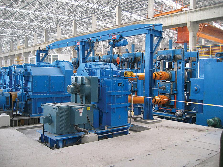
Figure 1
Compared to a conventional drive system, a more versatile system has one drive unit—an AC motor and a pinch roll output reducer—per roll stand. Photo courtesy of Milltech.
As mill designers found justification in using individual drives for large mills, the inevitable happened: It spread to small mills. It hasn’t reached all small mills, but the technology is justified in mills that carry out specialized applications, such as those that form high-yield-strength materials, or form materials with low diameter-to-wall-thickness ratios, or that form at fast processing speeds.
That’s not the end of it. Combinations of these variables added enough complexity to the system that in some cases, an individual drivetrain for each roll stand still isn’t enough to maximize efficiency. In some cases, it’s actually cost-effective to use two motors per stand: In this type of unit, a process-optimizing drive system (PODS), one motor unit drives the top roll and the other drives the bottom roll (see Figure 3).
This system offers tube mill operators unlimited flexibility in various facets of mill operation:
It’s necessary to keep in mind that, even after the mill drive speeds are optimized for a product size, the work isn’t quite done. The PODS speeds have to be set for each size of product run on the mill, and a mill that runs several materials in a common size sometimes needs the drive speeds optimized for each material. This has to do with the strength (hardness) characteristics of each material, the wall thickness, and maintaining the necessary tension between stands.
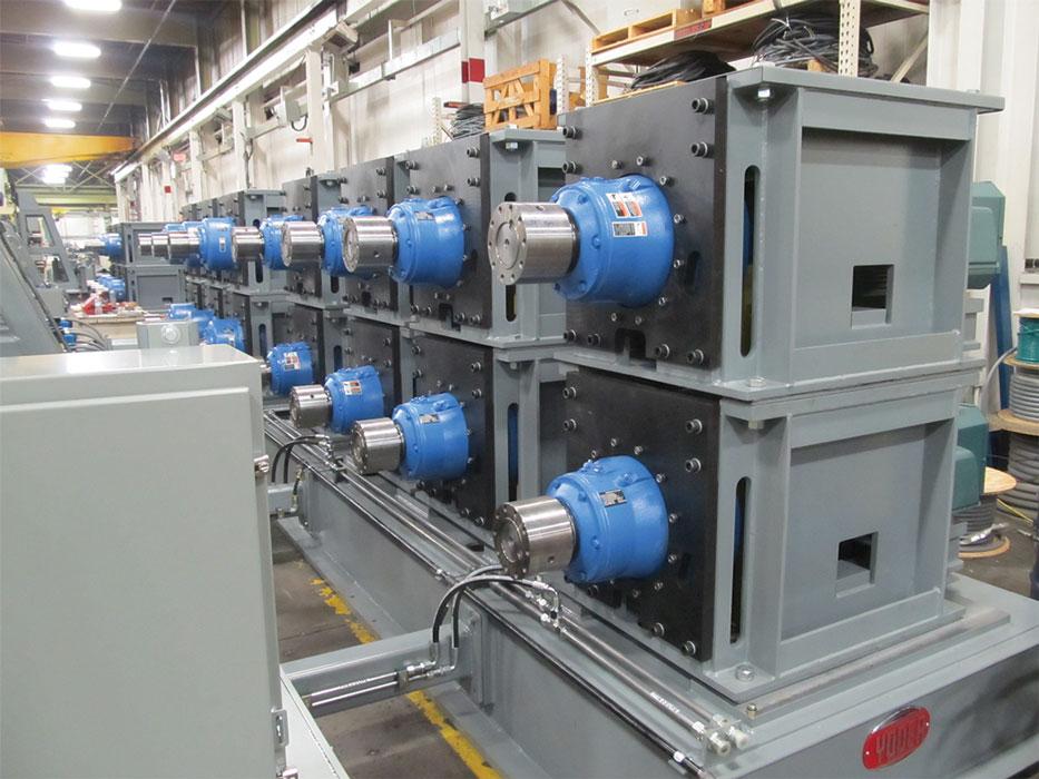
Figure 1
A third type of drive system uses two motors and pinch roll output reducers per roll stand. One unit drives the top roll and the other drives the bottom roll. Photo courtesy of Formtek Inc. – Yoder.

The Tube and Pipe Journal became the first magazine dedicated to serving the metal tube and pipe industry in 1990. Today, it remains the only North American publication devoted to this industry, and it has become the most trusted source of information for tube and pipe professionals.
start your free subscription
Easily access valuable industry resources now with full access to the digital edition of The Fabricator.

Easily access valuable industry resources now with full access to the digital edition of The Welder.

Easily access valuable industry resources now with full access to the digital edition of The Tube and Pipe Journal.

Easily access valuable industry resources now with full access to the digital edition of The Fabricator en Español.
Seth Feldman of Iowa-based Wertzbaugher Services joins The Fabricator Podcast to offer his take as a Gen Zer...


