


President
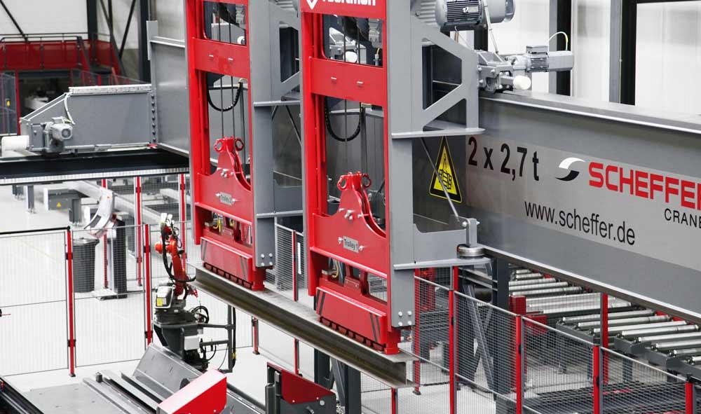
A material handling system picks up the workpiece after it exits the beam line and positions it for automated welding.
The structural steel fabricator has developed into a lean, mean machine, but automation in this industry has a long and interesting history. Most structural fabrication operations of the past were labor-intensive. Layout, drilling, cutting, and welding were performed manually. In structural fabrication today, nearly every process can be automated. Few if any other metal manufacturing sectors could make such a claim.
Structural fabricators stepped into beam line automation with machines like the Beatty punch, followed by the three- and five-press beam punch lines. The beam punch lines of the 1970s were the first step. They reduced the manual labor required to process main structural members by punching the holes in all surfaces in one pass. A saw could be added on the same system to cut members to length.
The next progression was the “pop mark,” an early way for a beam punch line to make layout marks on a beam. Using the tip of the punch, a machine could mark the centerpoint of the piece and the intersection for weldments, plate, and angle connection points.
Dealing with mill tolerances was the next challenge to overcome for machines of the late 1970s and early 1980s. Machines had to be designed to detect all the conditions of the piece to be processed. This included toed-in or -out flanges, off-center webs, twist, and camber.
The structural drilling and sawing line was the next development, and in the early 1980s drills were quickly replacing the beam punch lines of the past. The weight and thickness restrictions of material diminished, paving the way forward.
In some cases, though, the beam punch line was even faster on lighter material. There was a saying at one time: Punch for profit, drill for oil. The saying was true; the cost per punched hole was considerably cheaper than the cost per drilled hole, although this did not offset the total benefits of drilling. The punching system was not as flexible as the drill, and the punch had restrictions based on the punching tonnage available.
Early automated coping machines of the mid-1980s were simple systems with no linear measuring that could prepare basic end-connection detail using three oxyfuel torches.
The next generation of coping machines could produce far more complex cuts such as copes, notches, rat holes, weld preparation, slots, web penetrations, split tees, and castellated beams, to name a few.
By the late 1980s, downloading of data from 3-D CAD systems became a reality. The basic cut-to-length, hole position, pop marks for part location, piece number, and cope information was held in the DSTV file format, which was developed in Germany and became a global standard. Many versions later, this format is still used today, but the file holds far more information.
In the 1990s the cold saw was phased out at many plants and replaced with more cost-effective methods, such as band sawing. Typically, the band saws were placed in tandem with the drill; this saved space and required only one operator. The CNC positioned both the saw and the drill before transferring the beam to a coping machine.
Multisystem integration (MSI) integrates multiple metal fabrication machines with material handling systems. The links allow the entire structural fabrication system to operate as a single, automated unit.
The industry soon witnessed the evolution of plate processing. Structural fabricators moved from the traditional burn table with multiple oxyfuel torches to a pass-through-style system in which the material moved and the machine remained fixed. Such combination systems could either punch and plasma cut or punch, drill, and plasma cut. The oxyfuel torch was retained on certain models for thick materials.
The pass-through systems used nesting programs to minimize scrap. They also dropped off the finished part rather than requiring an operator to remove it from a table or shake it from a skeleton. The “stock material on, part off” concept revolutionized plate production, especially in structural steel shops. Along with downloading data from CAD, this concept allowed structural fabricators to produce standard parts. This reduced plate inventory and allowed designers to work with certain design parameters to create standard connections. All this boosted fabrication efficiency.
During the 1990s the industry began to notice the obvious constraints of material handling. They included the labor cost associated with moving steel through processing to fabrication and ultimately getting the correct detail parts (that is, those parts to be connected to beams) to the weld stations.
Many different material handling methods were used. Workers sometimes pushed beams on simple trolleys from station to station. Sometimes they operated a motorized system capable of positioning multiple beams at one time for each station.
It was estimated a fabricator touched a beam up to 15 times at an approximate cost of $25 per lift. For this reason, material handling became a huge focus for the fabricator to reduce labor-hours and cost.
By 1998 the industry witnessed early automated material handling technology that loaded and unloaded a simple drill-saw tandem system. Fabricators in North America began to see hydraulically driven rollers and transfer systems. These hydraulic systems required an operator at each processing position, so they had high labor costs. The hydraulic system is still widely used today, but is being phased out.
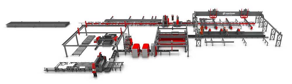
Today’s automated systems—known as multisystem integration, or MSI— position workpieces using electric motors, inverters, and encoders. Monitoring the position of each piece, the MSI combines multiple machines into one production line. Once the production requirement is created and material is loaded, an MSI operates without manual input.
For example, material moves from a shotblasting machine to a drill machine, a layout marking machine, a sawing machine, and finally a plasma and oxyfuel robotic structural cutting system. All machines are mechanically connected to each other by roller conveyors and cross transports.
The production process starts at the detailing office where the project is created in a 3-D CAD system. Each product is broken down into a DSTV file that is then imported into the machine’s software. After this step, nested files are generated in a DSTV+ format, which is then uploaded to the master control of one of the machines. The product is then distributed from the master to all machines in the production line. Because every machine is connected to the master, each one always has the most up-to-date production data available.
Today the operator simply selects the loaded profiles on the control panel and starts the process. Data then is updated automatically at the production office and at every machine. The material handling system has built-in buffers so the production line knows the order in which the beams go through and which processes are required on each piece.
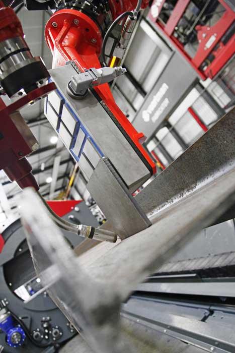
Automated welding has now reached the beam line. Before striking an arc, the welding gun touches off the wire tip to ensure accurate positioning.
Cross transports with photocells detect the profiles and position them at the correct distance apart for the shotblasting of multiple pieces in one pass. Immediately after processing, transfer mechanisms move the beams to the next operation. Encoders and sensors in the roller conveyor register the exact position of the batch. When the sensor on the infeed control is passed, a new batch of beams is transported onto the infeed conveyor. The new batch holds position until the first bundle passes the outfeed sensor. The height of the beams is monitored to ensure the dimensions comply with the data in the software, and the height of the brush and blowoff unit is adjusted to remove any blast media from the web area before the beam moves to the next operation.
Cross transports between two machines function as a buffer to equalize differences in production speed. Beams on the cross transports are automatically repositioned to create enough space for the next bundle of beams. The software knows the beam positions and dimensions to ensure all operations connect seamlessly to each other—and all of this is followed in real time by the production office.
Mechanical drag-dogs move beams rapidly over the cross transports to minimize transfer time between machines. Before the beam crosses the infeed roller conveyor, the feed slows as it approaches the datum line to prevent damage.
A servo-driven feeder truck moves the beam, and at the same moment, the roller conveyor moves the beam toward the servo-driven feeder truck. This also reduces the transfer time. The beam is then processed while the next beam is transferred close to the infeed roller conveyor.
Short pieces (less than 47 in. long, for example) are removed and pushed sideways into a bin by a short product removal system. Leading and trailing edge trim cuts are removed and deposited in the scrap bin with no manual intervention. Finally, the long pieces are transported to the outfeed cross transports and are removed.
The next step, now a reality but still in the early stages of adoption, is adding robotics to the structural fabrication shop. Robotic welding and thermal cutting are not new to structural fabricators, but automated welding is—that is, welding with no manual intervention whatsoever. This includes program development and moving material in and out of rotating fixtures.
Two technology advancements make fully automated robotic welding possible. First, weld programming in these systems now can be automated. Traditionally, robotic welding systems still require programming, so a structural fabricator usually takes a welder and makes him a programmer. But the goal is to reduce overhead and increase efficiency, not increase the labor burden.
Second, robots use sensors and probes (including the use of the welding wire tip as a touch probe) to measure and adapt to workpiece variation. For instance, intelligent systems now can probe toed-in or -out flanges, off-center webs, and whether material is within mill tolerances.
Intelligent welding systems can import data from CAD, if the welding information is in the model. If it is not, a database can recommend the welding information to add to the model; a programmer then can take this recommendation or add in the welding information separately.
At the end of the beam line, beams are automatically loaded into the welding system. From here the detail (that is, the part to be welded onto the beam) is transported, deburred, scanned, and positioned correctly so that the material handling robot can place the part on the beam. Using the wire tip as a touch probe, the welding robot detects the beam’s true position, then tacks the part. Finally, when all the parts are tacked in position, the robot arm welds the pieces.
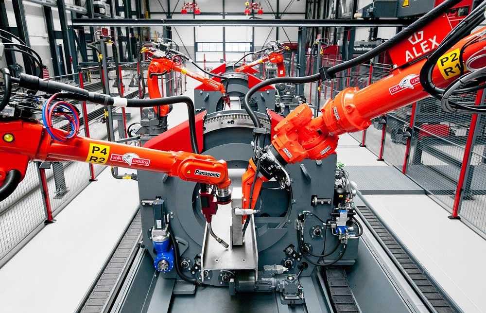
A beam is moved into position as a material handling robot positions a vertical plate for welding onto the web section.
The industry has moved from manual fabrication to comprehensive automation. The leap has been a large one, with massive reductions in labor and huge increases in output, and technology will continue to drive the industry forward.
This isn’t to say that every modern structural fabricator has become fully automated. The rate of technology adoption varies widely within the industry, and it has always been this way. Indeed, many may be surprised to find that some of the technologies described here have been around for so many years.
Some structural fabricators continue to move closer to full automation, while others remain manual in many respects. Regardless, automation technology is available, while skilled labor increasingly is not.

The Fabricator is North America's leading magazine for the metal forming and fabricating industry. The magazine delivers the news, technical articles, and case histories that enable fabricators to do their jobs more efficiently. The Fabricator has served the industry since 1970.
start your free subscription
Easily access valuable industry resources now with full access to the digital edition of The Fabricator.

Easily access valuable industry resources now with full access to the digital edition of The Welder.

Easily access valuable industry resources now with full access to the digital edition of The Tube and Pipe Journal.

Easily access valuable industry resources now with full access to the digital edition of The Fabricator en Español.
In this episode of The Fabricator Podcast, Caleb Chamberlain, co-founder and CEO of OSH Cut, discusses his company’s...


