Contributing Writer
- FMA
- The Fabricator
- FABTECH
- Canadian Metalworking
Categories
- Additive Manufacturing
- Aluminum Welding
- Arc Welding
- Assembly and Joining
- Automation and Robotics
- Bending and Forming
- Consumables
- Cutting and Weld Prep
- Electric Vehicles
- En Español
- Finishing
- Hydroforming
- Laser Cutting
- Laser Welding
- Machining
- Manufacturing Software
- Materials Handling
- Metals/Materials
- Oxyfuel Cutting
- Plasma Cutting
- Power Tools
- Punching and Other Holemaking
- Roll Forming
- Safety
- Sawing
- Shearing
- Shop Management
- Testing and Measuring
- Tube and Pipe Fabrication
- Tube and Pipe Production
- Waterjet Cutting
Industry Directory
Webcasts
Podcasts
FAB 40
Advertise
Subscribe
Account Login
Search
Tips for creating sheet metal tubes with perforations
Fold/Unfold tools in 3D modeling can be handy for this type of work
- By Gerald Davis
- April 23, 2024
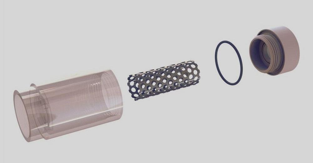
FIGURE 1B. The Exploded View also can be used to make illustrations. Here, the model is rendered to indicate the various plastics and metals for the components.
Editor’s Note: CAD files associated with this column can be downloaded here.
Exploded Views and their various methods and merits were discussed in the previous episode. In this column, the conversation continues.
Figure 1A presents a 2D drawing using an Exploded View and a corresponding bill of materials (BOM) table. A drawing might include balloons to tie rows in the BOM table to identified components in the Exploded View.
The Exploded View is stored in the 3D model’s file. Figure 1B is using the Exploded View used in Figure 1A for a different purpose. The goal is realism as opposed to detail for procurement. Such an image might be useful in a service manual.
With the 3D model’s Exploded View collapsed into its normally assembled condition, Figure 1C displays the 3D model with the Cross Section tool turned on. Cross-sectioning allows items to be excluded from the sectioning. In Figure 1C, one could note that the option to exclude at least one item is in use.
Section Views, unlike Exploded Views, are created and exist independently in both the model and the drawing. Thus, the Figure 1C won’t be useful in a 2D drawing but could be duplicated by using the drawing’s Section View tool.
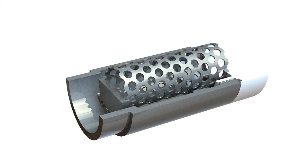
The ulterior motive behind all of the preceding figures is to bring attention to the perforated sheet metal tube, the topic of this episode.
On With the Show
A modeling sequence for the tube is shown in Figure 2A. (Disclaimer: While many possible workflows exist, this is simply how it came to be for the author.) The first modeling step is to create a Revolved Body by spinning a sketched rectangle about an axis for about 340 degrees, in this example.
In the olden days when PC computers were slow and modeling technique mattered significantly to rebuild time, Revolved Bodies were recommended (over Base Extrudes) for speed. This especially held true for things like pulleys, where one revolve can do the work of several Base Extrudes.
The second modeling step calls for adding a flat space (a Base Extrude) for the Jog Bend tool to bend. It is not obvious in the illustration, but the Convert to Sheet Metal tool was applied in preparation for the third step.
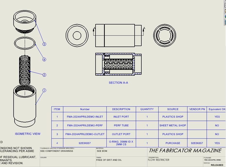
FIGURE 1A. An Exploded View from a 3D model is used on a 2D drawing to reveal the components in an assembly. Here, a bill of materials table has procurement detail for each component in the isometric view.
The third modeling step adds a jog bend. As a side note, the author now wonders if this is the most efficient workflow. Because modeled sheet metal will create errors if it intersects with itself, the revolve was made with an excessively wide gap to make room for the jog bend. Now that gap has to be closed.
The fourth modeling step adds a Sketched Bend to hump the jog a few degrees so it ends up closer to being tangent to the tube. The gap was closed using the Move Face tool. Yes, this would be a thrill to bend, but it is easy to model.
In Figure 2B, a flat advantage of sheet metal comes to bear. The fifth modeling step uses the Unfold tool (collecting all bends) to flatten the part. The Fill Pattern tool is then applied to model the pattern of 5/32-in. holes on 7/32-in. staggered centers.
And of course, the sixth step uses the Fold tool (collecting all bends) to refold the part, ready for welding.
There are consequences to using pre-perforated sheet stock. When sheared, scimitar hooks are created as holes are sliced. The Fill Pattern tool allows the pattern to be oriented at any angle, which might reduce the scimitar hazard.
In Figure 2C, the Fill Pattern has been rotated 90 degrees, leaving a lovely edge near the jog bend. The Fill Pattern tool also allows one to set a margin for the pattern to completely avoid the slicing through holes, but that is digression. The point here is that Fill Pattern and Fold/Unfold can be speedy tools for otherwise tedious modeling.
subscribe now

The Fabricator is North America's leading magazine for the metal forming and fabricating industry. The magazine delivers the news, technical articles, and case histories that enable fabricators to do their jobs more efficiently. The Fabricator has served the industry since 1970.
start your free subscriptionAbout the Author
- Stay connected from anywhere

Easily access valuable industry resources now with full access to the digital edition of The Fabricator.

Easily access valuable industry resources now with full access to the digital edition of The Welder.

Easily access valuable industry resources now with full access to the digital edition of The Tube and Pipe Journal.
- Podcasting
- Podcast:
- The Fabricator Podcast
- Published:
- 04/30/2024
- Running Time:
- 53:00
Seth Feldman of Iowa-based Wertzbaugher Services joins The Fabricator Podcast to offer his take as a Gen Zer...
- Industry Events
Pipe and Tube Conference
- May 21 - 22, 2024
- Omaha, NE
World-Class Roll Forming Workshop
- June 5 - 6, 2024
- Louisville, KY
Advanced Laser Application Workshop
- June 25 - 27, 2024
- Novi, MI
Precision Press Brake Certificate Course
- July 31 - August 1, 2024
- Elgin,

