


Is the press brake or tooling really to blame?
Even the latest machines and tooling must deal with material variation
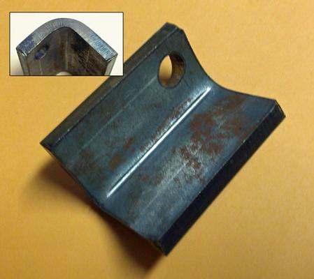
Figure 1
A crease down the center of the inside bend radius is a telltale sign you’re bending sharp.
Question: My company purchased two new press brakes that, even though they’re maxed out with options, really don’t meet our needs. We are still running into issues, like not being able to keep repetitive angles. Our tooling is new, and the precision-ground punches really help us shorten setups. But for us, achieving consistent angles is the real headache.
We primarily form 10-gauge up to 0.25-in.-thick mild steel, and I am wondering if our material has a lot to do with it. If so, what type or grade would be better to use? Or is there another route I can take to correct our problem with inconsistent angles to maintain our one-piece flow?
Answer: Let me begin by saying that we all have a personal preference when it comes to press brake makes and models. Drive systems, whether they are electric, hydraulic, or servo-hydraulic, might work in different ways, but they all offer repeatability in micrometers.
Press brake manufacturers do offer proprietary options that might make or break a particular application, but that’s nuance. When it comes to basic capabilities, most major brand-name machines are as good and as accurate as any other. The same thing can be said for tooling. If you stay within a particular group, such as precision-ground or planer styles, and match the work you have to a given type of tooling, you can achieve excellent results.
It’s also safe to say that if you’re looking for the best results on modern press brakes, you’ll need precision-ground tooling, which usually has manufacturing tolerances of ±0.0004 to ±0.0008 inch and share a common height and tool center. Planer tooling holds tolerances of ±0.005 in. over 10 feet, which makes it difficult to use in a staged press brake setup.
Even then, neither the tooling nor the press brake should ever be used to their full capacity. Never use any machine to its maximum or minimum, but rather its optimum. For safety reasons, it’s best for the press brake and tooling to have at least 20 percent more tonnage capacity than the job requires.
Thickness and Tensile Variation
Even though your new press brake and tooling can perform to high levels of accuracy, you still need to take material variation into account—especially if you have tight-tolerance work. Editor’s note: For more on this, see “Reasonable tolerancing for press brake bending,” archived at thefabricator.com.
Take 10-ga. hot-rolled steel as an example. Its nominal thickness is 0.1345 in. but can range from 0.1285 to 0.1404 in. The material thickness also can vary across the width of the sheet. At the mill, the rollers deflect in the center, causing the plate or sheet to be thicker in the center and thinner near the edges. This can create a several thousandths of an inch difference in thickness. Let’s say the thickness varies 0.007 in. from the edges to the center. That’s enough to cause as much as a 5-degree bend angle variation from workpiece to workpiece.
All materials also have an ultimate tensile strength (UTS) tolerance. Say you’re working with 10-ga. ASTM A36 steel. The zone of UTS tolerance is 58 KSI all the way up to 80 KSI.
Hot-rolled Versus Cold-rolled
Hot-rolled and cold-rolled steel have some very basic differences. Hot-rolled steels are rolled at high temperatures, and they can have a lot of residual stress caused by uneven cooling. That residual stress can exacerbate part-to-part variations.
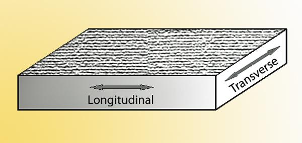
Figure 2
Bending with (longitudinal) rather than against (transverse) the material grain can produce very different results.
Cold-reduction mills further transform the steel by rolling it again, usually at room temperature, then annealing or tempering it. The process gives cold-rolled steel a far superior surface finish when compared to hot-rolled pickled-and-oiled steel. Also note that cold-rolled sheet usually is a low-carbon product that’s typically in an annealed state, softer than hot-rolled steel, while hot-rolled steel usually is much stronger. Editor’s note: For more on this, see “Material grain considerations for the press brake,” archived at thefabricator.com.
Effects on Radius and Bend Deduction
Let’s assume we’re forming a “perfect” bend radius, one where the material thickness and inside bend radius are the same. This can lead to stable, repeatable bends—but you still need to take that material variability into account.
First, let’s consider material thickness variation. Again, 10-ga. material ranges from 0.1285 to 0.1404 in.; that’s a 0.0119-in. difference. When we run our bend calculations, different thicknesses give us different bend deductions (BDs). Run the calculations for 0.1285-in.-thick material and we get a BD of 0.222 in.; run the same calculations for 0.1404-in.-thick material and we get a BD of 0.243 in.—a difference of 0.021 in.
The changes in tensile strength described previously also affect the inside bend radius. In an air form, the higher the material tensile strength, the larger the floated radius will be. Change the radius and you change the BD.
Small Radii and Sharp Bends
You noted that you are using top-quality tooling, but you didn’t mention anything about the specific punch nose radii or the final inside bend radii of your parts.
If you are using a punch nose radius that’s too small for the application, you can go into the “sharp” realm. These punches apply a lot of force to a small area. Depending on your length of bend, your punch nose might be beginning to pierce the surface of the material.
Generally, bends become sharp when you try to achieve an inside bend radius that’s less than 63 percent of the material thickness. You can identify a sharp bend by the telltale crease in the center of the inside bend radius (see Figure 1). Try as you might, you cannot put a smaller inside radius into that sharp bend; the narrow punch just digs deeper into the bend line.
Bending sharp will amplify all the effects of your bending variables, including your bend angle, and subsequently will affect the measured linear dimensions of the bend. The operator forms a bad (out-of-tolerance) bend angle, then makes things worse by gauging off those bad bend angles.
The quality of the sheet and plate also affect the consistency and appearance of the product. The rolling of steel at the mill produces the material grains in the direction of rolling, and these grains affect how sheet or plate behaves. Less expensive material tends to include more impurities, a larger grain size, and therefore is more susceptible to variations in the bend angle. Grain characteristics also vary from sheet to sheet and batch to batch (see Figure 2).
When you bend small inside bend radii longitudinally to the material grain (with the tooling parallel to the grain direction), you increase the possibility of cracking on the bend’s outside surface. This again causes angular variation from sheet to sheet and batch to batch, especially when you’re bending sharp.
Nesting Complications
Again, sheet and plate steels have a grain direction, with cold-rolled steel showing a more pronounced directional preference than hot-rolled steel. Depending on the bend line’s relationship to the grain, the effects to the bend angle will differ.
You might be processing parts that were cut from an optimized nest layout, in which you place as many parts as you can on the sheet regardless of grain direction. If no two parts maintain the same grain-to-bend-line relationship, you could be making the bending operator’s job almost impossible.Consider a Small-batch Model
Now, the usual disclaimer: Bending problems come from a host of variables, and it’s difficult to pinpoint the root causes without the complete picture. Regardless, I believe you might be right: The problem probably is related to the material—including the order in which that material flows through the brake department. You mentioned that you need to maintain your one-piece flow, or single-piece-pull, environment.
Single-piece pull works in many places within manufacturing, but your shop’s press brake department might not be the best place to apply the concept. Even with the new machines and tools you describe, in a single-piece-pull environment your operators are having to remove and replace tools frequently. All those manual setups add yet another variable to an already highly variable process. You might consider replacing the single-piece pull with a small-batch model. This will allow for fewer setups and more consistent parts without the hassle and expense of large-batch manufacturing.
About the Author

About the Publication

subscribe now

The Fabricator is North America's leading magazine for the metal forming and fabricating industry. The magazine delivers the news, technical articles, and case histories that enable fabricators to do their jobs more efficiently. The Fabricator has served the industry since 1970.
start your free subscription- Stay connected from anywhere

Easily access valuable industry resources now with full access to the digital edition of The Fabricator.

Easily access valuable industry resources now with full access to the digital edition of The Welder.

Easily access valuable industry resources now with full access to the digital edition of The Tube and Pipe Journal.

Easily access valuable industry resources now with full access to the digital edition of The Fabricator en Español.
- Podcasting

In this episode of The Fabricator Podcast, Caleb Chamberlain, co-founder and CEO of OSH Cut, discusses his company’s...
- Trending Articles
1
Capturing, recording equipment inspection data for FMEA

2
Tips for creating sheet metal tubes with perforations

3
Are two heads better than one in fiber laser cutting?

4
Supporting the metal fabricating industry through FMA

5
Omco Solar opens second Alabama manufacturing facility
