


Senior Editor
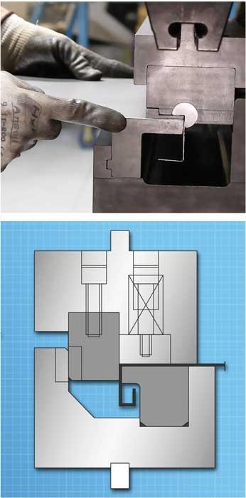
Horizontal bending tools for the press brake generally are available in two varieties: the rotary bending tool (top) and the wiping tool (bottom). Images courtesy of Wilson Tool International.
A press brake may have sufficient safeguarding, including light curtains on the sides and cameras or lasers detecting objects just below the punch tip. But all the safeguarding technology in the world can’t make the press brake operator’s back feel better.
Historically it’s been common to see two brake operators straining to lift a large panel as it whips up during the forming cycle. Working with thin panels, they take care to support the work to ensure gravity’s effect on the portion of the workpiece whipping upward doesn’t distort the resulting bend. They also take care to get out of the workpiece’s way. Being hit by a workpiece whipping up during the bending cycle isn’t very pleasant. A press brake that is lifting a large unsupported workpiece during the forming cycle also can increase the forming tonnage required.
Fabricators usually tackle this problem in several ways. At the very least, the press brake has supports in the front that help operators position the workpiece against the backgauges. They also may have something other than a human lift to support the part as it arcs upward during the press brake’s bending cycle. This could include some type of crane or hoist, the most common choice for thick plate.
For thin sheet, fabricators have options, including a sheet follower. The sheet follower does just what it says. Positioned in front of the press brake bed, the device supports and follows a large sheet as it whips upward during bending.
Another approach involves changing how bending occurs. Instead of both the short and long legs of the bend whipping upward as the punch descends into the V die, the long leg stays horizontal while the short leg bends upward or downward. For making edge flanges in large panels, this makes all the sense in the world.
Fabricators have several ways to accomplish this: with special tools on a press brake or a different machine altogether, such as a panel bender or folder. As with any technology, each machine and tooling choice has its limitations. But for the majority of sheet metal applications, fabricators have a plethora of options.
The press brake can use a range of special tools, but when it comes to horizontal bending—that is, where the sheet in front of the tooling remains horizontal during the bending cycle—two categories of tools are available: wiping and rotary-style.
Wiping tools work as they sound: A punch essentially wipes the sheet against the die. Wiping could be described as a bottoming operation, and each die set is made for a specific material type, thickness, bend angle, and radius. As such, wiping requires significant tonnage, which is why you rarely see wiping operations for mild steel thicker than about 0.125 in. Most wiping tools are made to form 90-degree bends, but some custom wiping tools can be made to form workpieces to other angles.
“Because the tool is designed for a specific material thickness, slight variations in material thickness can cause quality problems,” said Greg Flaherty, design engineer and press brake specialist at Wilson Tool International®, White Bear Lake, Minn. “The gap between the forming punch and stationary die is critical. If the material is a little thicker than what the gap is designed to handle, the wiping action tends to mark or gall the material. If the material is thinner than the gap, you’ll end up with an underbent angle. In traditional air bending, you’d simply descend the punch a little farther to achieve the angle you need. But in a wiping situation, you’re stuck with
He added that springback sometimes can be difficult to control. The wiping punch wraps the sheet metal around the die, but once the cycle completes and the pressure is released, the bend angle can relax slightly.
Some wiping dies can be made so they press slightly into the material at certain points, mitigating springback. But Flaherty cautioned that sometimes this isn’t ideal. The punch pressing the material into the wiping die may mitigate springback, but it also coins the workpiece, which can mar it and cause material integrity problems.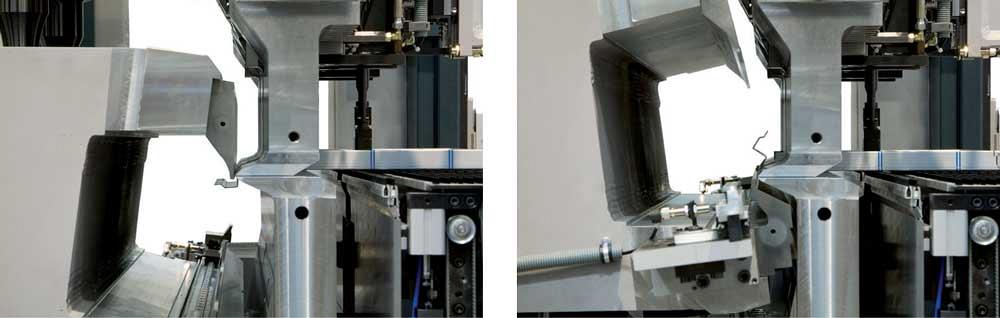
In panel bending, hold-down tools clamp the workpiece in place, while bending blades form the workpiece in the positive and negative direction. Photo courtesy of Salvagnini America Inc.
“Rotary-style horizontal bending tools can form edge flanges in a much more controlled manner,” Flaherty said.
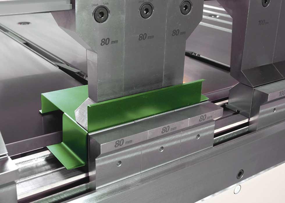
Rotary tools consist of a Pac-Man-shaped cam that sits in a saddle, basically a circular pocket in the tool. The operator slides the sheet to the back of the tool. As the press brake ram descends, the cam wraps the material around the die, which is called the anvil.
“The anvil is recessed, so you can overbend a few degrees to account for springback,” Flaherty said.
To form a flange down, the cam is part of the upper tool, which descends downward to form the bend over the anvil. To form a flange upward, the cam is part of the lower tool; in this case, the anvil descends toward the rotating cam.
“You can also bend different angles by adjusting the stroke of the ram,” Flaherty said, adding that a rotary tool can bend included angles anywhere between 75 and 135 degrees, while some tools can form open angles up to 145 degrees. They’re usually used for material that’s 0.25 in. and thinner, but Flaherty did say that custom tools sometimes can be designed to handle thicker stock. This is accomplished by building a larger cam, which gives the rotary tool a larger opening.
The rotary tool can account for variations in material thickness. If, say, the tool underbends, and the included angle ends up being slightly more open than it needs to be, the operator can adjust the ram position to add a few more degrees for overbending.
Horizontal bending tools allow for multiple-bend geometries like return flanges consisting of two or more bends. But these tools do have flange depth limitations. The tool size governs the flange depths you can achieve. Of course, as the tool size grows, so does the expense.
Horizontal bending large workpieces on a press brake still requires operators to lift and support the sheet in some way. Two or more workers may hold the sheet in place, or they may use a support table to position the large panel for bending.
Alternative technologies, though, take another approach to bending altogether, which in turn changes how operators handle the workpieces—as well as the number of operators (often just one) needed to handle large sheets.
To form a workpiece on a folding machine, an operator (or automation) places a workpiece on a backgauge table, which has recessed rails with pop-up fingers, each individually controlled. The piece slides forward and is positioned under clamping beam tools that clamp the workpiece in place.
In recent years folding machines have been able to form in both positive and negative directions with a single beam. Image courtesy of RAS Systems LLC.
Backgauge tables are sometimes L-shaped, with the horizontal leg of the L behind the folding tools. When working with large panels, many folding machine operators prefer to work from behind the machine, and an L-shaped backgauge table allows them to support the work throughout the folding cycle.
The height of the clamping beam tools generally determines the height limit for a 90-degree flange in a four-sided box. If the workpiece has flanges on only one or two sides, folders have no limit on flange heights. The clamping beam tools are changed and rearranged to accommodate different bend lengths while avoiding collisions with previously formed flanges.
Once the machine has material clamped, a tool on a swinging beam contacts and folds the workpiece. “The beam can swing to a position within 0.1 degree, resulting in an angle tolerance of plus or minus half a degree,” said Bill Kennedy, vice president of RAS Systems LLC, Peachtree City, Ga. “Standard tooling is very flexible, and there are no tool changes required to accommodate different material thicknesses.”
Some machines offer a height-adjustable backgauging table, which can help operators run more kinds of parts—say, to support a negative bend. “You can drop down your backgauge table to gauge off of a negative bend,” said Chandler Barden, national sales manager for CIDAN Machinery Americas, Peachtree City, Ga.
Folding machines also can form hems and other edge geometries. The operator slides the part onto the backgauge table, and the clamping beam tool descends to form the hem, be it flat, teardrop, or another shape.
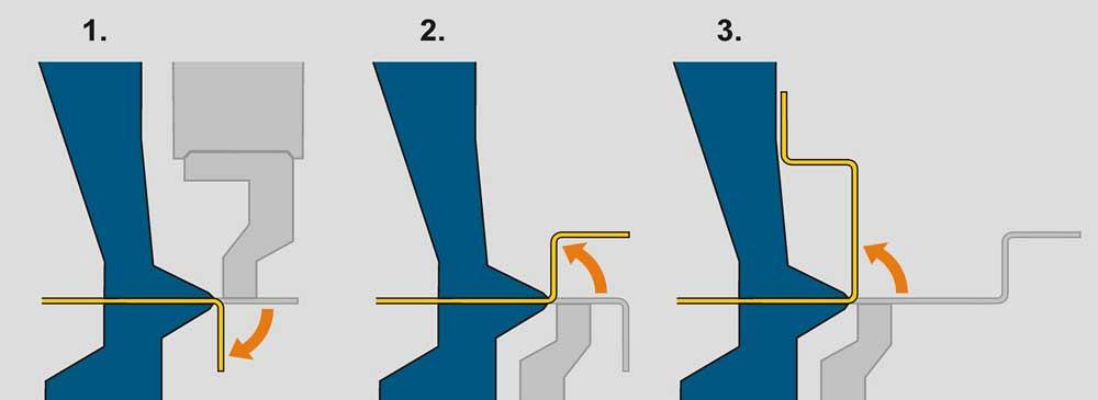
Decades ago folding systems created only positive bends, like edge or return flanges around a box or panel, but modern folding systems can create both positive and negative bends. The folding beam does this by swinging upward and downward. To swing downward, it must pivot outward by the width of the folding tool. Say the beam tool is 0.6 in. wide. For the first upward bend, the top edge of the tool contacts the sheet to make the bend. To bend downward, the tool’s bottom edge must fold the material surface. This requires the beam’s pivot point to move 0.6 in.
“Also, the folding beam itself is a powered axis and can be adjusted out as much as 5.9 in. to avoid any collisions with a previously bent flange,” Kennedy said.
Thicker tools on the folding beam can accommodate thicker materials. Thinner tools can fold material only so thick, but these narrow tools also can access certain areas that thicker folding tools can’t, like the back-to-back bends required for narrow offsets.
Automatic tool change on press brakes has been growing in popularity, and in recent years tool change automation has hit the folding machine market too. “In these machines, robotic manipulators change and rearrange clamping beam tools for the job at hand,” said David Prokop, executive vice president of MetalForming Inc., Peachtree City, Ga.
Alternatively, some folding systems change tooling automatically by rotating the upper beam. One side of the beam can have a conventional clamping beam solid tool, while the other side of the beam can have segmented clamping beam tooling. As Barden explained, “An operator can do as many bends with the solid tool, and on the segmented side, he can have tools set up for panels of different widths and other parts.”
Like press brakes, folding machines now have automatic tool change options, only here the clamping beam tools are changed and manipulated to accommodate different bend lengths and avoid collisions with previously formed flanges. Photo courtesy of MetalForming Inc.
Some folders incorporate automation that helps eliminate manual loading and manipulation of large blanks. This, of course, improves operator ergonomics, which is often the primary reason fabricators purchase a folder in the first place.
“A lot has changed with folding technology to relieve the bottleneck in the forming department,” Prokop said. “Fully automated folding systems with auto tool change and part manipulation have hit the stage.”
In panel bending, the sheet is positioned below blank-holder tools, which descend and clamp the workpiece in place, with material protruding on the other side. The farther the metal protrudes beyond the tooling—an area of the machine called the throat—the higher the resulting flange will be. The deeper the throat, the higher the flange.
With the sheet metal in place, the machine’s bending blades from above and below move to fold the metal. For most operations, the motion of the bending blade, not the shape of the tools, determines the final bend angle and radius. The segmented blank-holder tools automatically change out to match the required bend lengths. And like the folding machine, panel benders can form special shapes like hems, with the bending blades forming material past 90 degrees and the hold-down tools descending to form the final hem.
Panel bending has evolved from being one type of machine to a technology incorporated into a variety of systems, from the manually fed to the completely automated.
Traditional panel benders use part manipulators that manipulate a part throughout the bending cycle. In this case, an operator inserts the sheet against locating devices, initiates a cycle, and the manipulator completes the entire part. Still other panel benders are integrated into fully automated cutting and forming systems. Sheet metal is cut, punched, and then formed on a panel bender, all on one extensive system.
In some systems, an operator places a blank against locating pins, and the machine makes all the bends on that side of the workpiece. Once those bends are complete, the operator rotates the workpiece, again places it against locating pins, and the panel bender takes it from there for all the bends on that edge of the panel. Alternatively, an operator can manipulate the piece between each bend if needed.
“Because it doesn’t have a manipulator to move the part in and out, it allows the machine to bend certain geometries that couldn’t be made using the manipulator,” said Paul Croft, bending product manager for Prima Power North America, Arlington Heights, Ill.
All these systems excel at high-product-mix production, considering that changeover times are minimal or nonexistent. Some have sheet size limits, depending on the machine model and how the sheet is manipulated during the bending cycle. Some offer features that allow for the machine to remove parts with a downward final flange. Some models have features that allow the systems to handle small parts, such as an integrated shear that can cut off a narrow part from a larger sheet. Others use a separate set of smaller hold-down clamping tools.
“[Consider a] door and frame of an electrical cabinet,” said Tom Bailey, TruBend product manager at TRUMPF Inc., Farmington, Conn. “They always consist of large panels and small channels. If you can do both, you have an ideal application for a panel bender.”
An adjustable-height backgauge table on a folding machine allows operators to form complex part geometries. Here, the table allows the operator to gauge off of a negative bend. Photo courtesy of CIDAN Machinery Americas.
The panel bender’s upside: Once a blank is introduced into the machine, either automatically or manually, all bends are performed automatically with no operator handling required. Between bending cycles, universal blank-holder tooling moves to accommodate different bend lengths, but that’s about it. No die width changes, no switching from a straight to gooseneck punch, or any of the other complications that come with press brake tooling. And the panel bender, like the folder and horizontal bending tooling on the brake, allows the worksheet to stay flat as the edge flange is bent.
As with any horizontal bending technology, a panel bender doesn’t work for every part. Depending on the system, interior windows and cutouts can prevent the manipulator from having enough surface to grip and move the work into position. And the part itself needs a flat or near-flat surface. Some panel bending tables have vacuums or brushes to accommodate a few downward-facing shallow forms, like a louver or emboss. But in general, the machine needs the part to have a flat surface to move the part from bend to bend.
To handle an even greater variety of parts, some panel benders are integrated as part of a system that incorporates both automatic-tool-change press brakes and panel bending. Parts labeled with bar codes arrive at the bending station that has one operator running both a press brake and a panel bender. The operator scans the bar code, which spurs either the panel bender or press brake into action.
“By the time the operator delivers the part to the bending machine, the program has been downloaded and the tooling arranged,” said Bill Bossard, president of Salvagnini America Inc., Hamilton, Ohio. “The machine forms the part, uses automatic angle correction as needed, then completes the job as the operator sends the formed part and retrieves the next, entirely different part.”
In this situation, the operator could form a small bracket on the brake, then retrieve a panel (or utilize conveyor automation) and position it on the panel bender, no heaving required.
Every option, from special brake tooling to automated systems incorporating several machines, has a business case to be made for it. Which to choose depends on a fabricator’s current and potential part and customer mix.
Regardless, choices abound. For operators straining their backs to lift a large panel through a press brake’s bending cycle, that’s a very good thing.
CIDAN Machinery Americas, www.cidanmachinery-americas.com
MetalForming Inc., www.metalforming-usa.com
Prima Power North America Inc., www.primapower.com
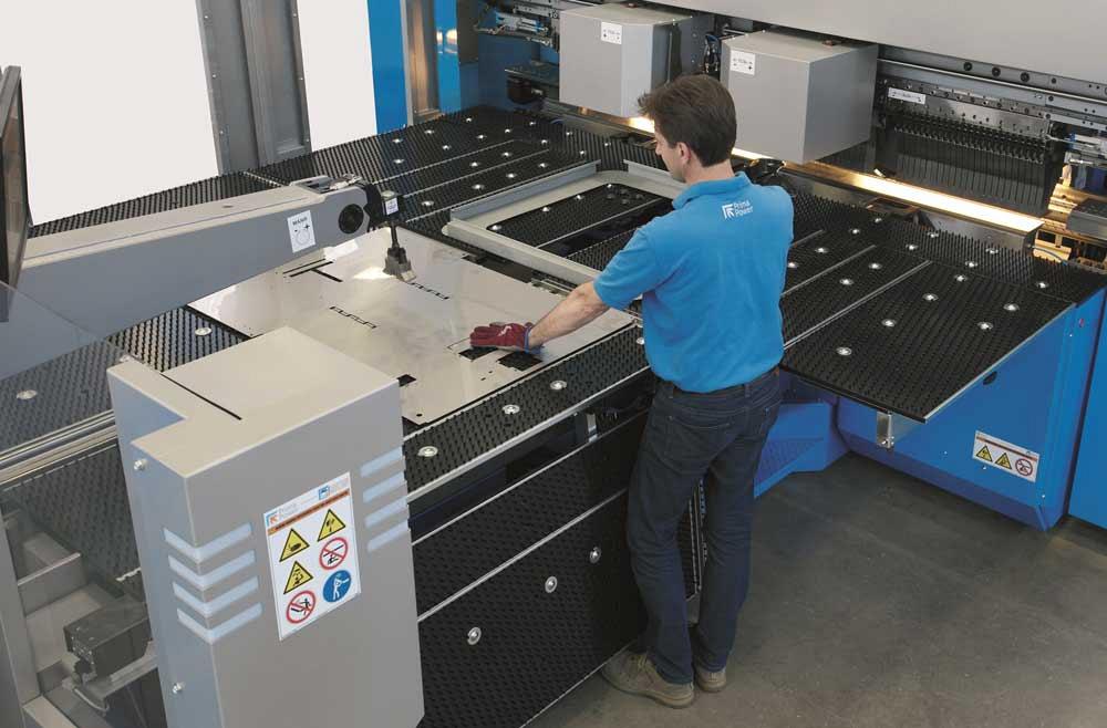
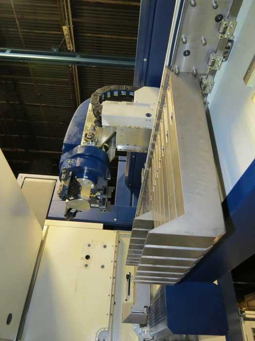
An operator positions a blank under a part manipulator, which moves the piece throughout the panel bender’s bending cycle. Photo courtesy of Prima Power North America Inc.
RAS Systems LLC, www.ras-systems.com
Salvagnini America Inc., www.salvagnini.com
TRUMPF Inc., www.us.trumpf.com
Wilson Tool International ®, www.wilsontool.com


The Fabricator is North America's leading magazine for the metal forming and fabricating industry. The magazine delivers the news, technical articles, and case histories that enable fabricators to do their jobs more efficiently. The Fabricator has served the industry since 1970.
start your free subscription
Easily access valuable industry resources now with full access to the digital edition of The Fabricator.

Easily access valuable industry resources now with full access to the digital edition of The Welder.

Easily access valuable industry resources now with full access to the digital edition of The Tube and Pipe Journal.

Easily access valuable industry resources now with full access to the digital edition of The Fabricator en Español.
In this episode of The Fabricator Podcast, Caleb Chamberlain, co-founder and CEO of OSH Cut, discusses his company’s...


