


Press brake bending basics: Die angles, tonnage, and K-factors
Recent questions from inquiring minds
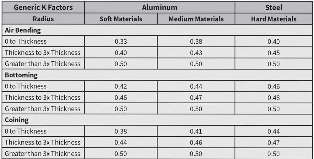
Figure 1
The K-factor varies with the forming method, material, and radius. A commonly used average value is 0.446.
What follows is just a sampling of questions I receive regularly. Keep the questions coming! There’s always more to learn, and the more you know, the more there is to know. It’s a lifelong adventure. Keep learning, my friends; it makes life much more productive.
Question: Usually we will form the bend radius so that it equals or is greater than the material thickness, but it also can be less than the material thickness. My doubt is why the inside bend radius should be considered equivalent or greater, and how does the K-factor and the neutral axis play a role in all this?
Answer: Many types of sheet metal have minimum bend radii assigned by the producer of the material. They include some aluminum alloys for which Alcoa and others list recommended and minimum inside bend radii by the specific makeup and characteristics of a given material.
An inside bend radius that we would consider a sharp bend can cause the material to develop stress cracks along the outside radius. These stress cracks are the manifestation of the grains in the metal tearing apart.
The material is expanded on the outside of the bend, compressed on the inside. The area that neither expands nor compresses is the bend’s neutral axis. Its length remains the same, but it does change position; it moves toward the inside surface of the bend.
How much it shifts depends on the material type and the method of forming: air forming, bottom bending, or coining. Figure 1 gives you a multiplier that, when applied to the material thickness, tells you the location of the relocated neutral axis.
An average and commonly used value for the K-factor is 0.446. We multiply this factor by the material thickness to determine the distance the neutral axis shifted toward the inside radius during bending. If a material is 0.062 in. thick, we multiply this thickness by the K-factor to arrive at 0.027652 (0.446 × 0.062). This tells us that the neutral axis moved from 0.031 in. (at half the material thickness) to 0.027652 in., or 0.003348 in. closer to the inside radius (0.031 – 0.027652 = 0.003348).
It does not seem like much, but it is enough to cause the bend to elongate. This is the reason the flat part is always smaller than the total outside dimensions of the formed piece (see Figure 2).
The sharper (smaller) the inside bend radius, the greater the stress on the material becomes on the outside of the bend. This increases the odds of cracking and part failure in the field. With bend radii equal to or greater than the material thickness, the less stress you put on the outside of the bend.
Also, if the bend radius is too small and too sharp, and the tonnage to form is too high, the punch nose radius will crease the center of the bend. This amplifies angular variations that occur because of changes to the material properties, such as thickness, grain direction, and hardness.
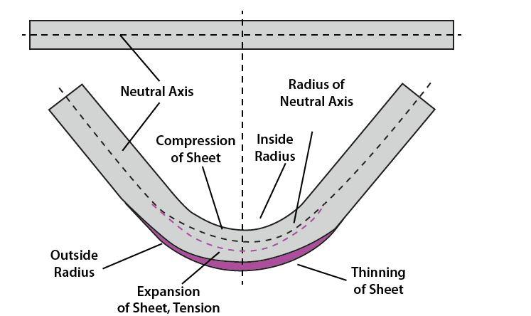
Figure 2
As bending occurs, the material’s neutral axis shifts inward toward the inside radius.
A bend radius that’s close to the material thickness will give you the most stable forming results, including consistent bend angles and final dimensions. That’s why it’s considered a perfect bend.
There are sound reasons for keeping the inside bend radius more than what would be considered a sharp bend and to use a K-factor value that is consistent with industry standards and applications. For more on this, you can refer to “What makes an air bend sharp on the press brake?” from November 2016 and “A grand unifying theory of bending on a press brake, Part I,” from September 2015, both archived at thefabricator.com.
Question: I read your article about why tonnage matters, and I have a question about the formula:
{[575 × (Material thickness)2]/ Die width}/12 = Tonnage per inch. Could you please explain where the 575 comes from and how the required angle factors into the formula? Do tonnages change if you are making an 85-degree bend versus a 125-degree bend?Answer: I have been unable to determine the origin of this tonnage formula. However, I do believe it dates back to the 1950s and most likely from the construction industry.
That 575 refers to the yield strength of mild cold-rolled steel. Today we have a large number of material types, and we multiply the result of the tonnage formula by material factor to get an accurate answer.
The basic formula you mention is for air forming cold-rolled steel. If you are bottoming, the tonnage is 3 to 5 times that of air forming, and if you are coining, the tonnage is 10 times or more. (For the complete formula incorporating factors for different material, forming methods, and special tools, check out “The 4 pillars of press brake tonnage limits” from April 2015, archived at www.thefabricator.com.)
Our baseline is cold-rolled steel with a tensile strength of 60 KSI. You can go to the web, check other materials’ tensile strength, and adjust your program accordingly. You do this by simply dividing your material’s tensile strength with the baseline of 60 KSI (or 60,000 PSI). For example, if your material has a tensile strength of 120 KSI, you divide that by 60 and get a material factor of 2.0. If you are working with soft aluminum with a tensile strength of 30 KSI, you divide that by 60 KSI and get 0.5 as your material factor.
The working tonnage calculations are made at the point on the stress-strain curve where the proportional limit of the material is, followed by a small increase in load as the yield point of the metal is reached. This is the value we use to compute forming tonnage.
And, yes, the tonnage required to form will change some when you are making an 85-degree bend versus a 125-degree bend. Still, once you bend past 20 degrees complementary, you already are using most of your forming tonnage anyway. In fact, about 80 percent of total forming tonnage is achieved within the first 20 degrees of the bend angle. In other words, even with a slight angle, a bend can put immense pressure on tooling and equipment.
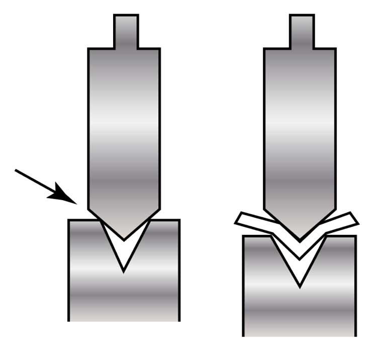
Figure 3
Mismatching the punch and die angle can create a dangerous situation. As the arrow points out, all the forming tonnage goes to the corners of the die opening. Under such stress, the tooling can split and, in some cases, explode.
Question: We bend alloy sheets ranging from 0.0393 to 0.0787 in. thick, with a radius that equals the material thickness. The punch is 88 degrees and the die 60 degrees. I can never get a 90-degree bend without having to compensate. What would be the optimal angle combination? And what would the perfect die opening be—8 times the material thickness?
Answer: You, sir, are doing something that is very, very dangerous, especially if you are using precision-ground tooling. However, there is a safe way to select your tooling; it is also the solution to your bending problems.
If the punch angle is the larger angle, it places heavy tonnage load along the top radii of the die—that is, the two top edges on either side of the opening (see Figure 3). In doing so, you create a fair amount of side thrust that will, if it hasn’t already, blow up the punch, the die, or both!
If you are using traditional planed-style tooling, you may hear a loud bang followed by the tooling falling to the floor—probably right on your foot. But if you’re using precision tools, watch out. Some precision tools can have Rockwell hardness ratings of 60 or even higher. If you blow a tool, it will throw shrapnel a long way!
OK, now that I’m done yelling at you, here’s what you need to do. First and foremost, your punch must have an included angle that either matches or is less than the die angle! You need clearance between the punch and die!
Finding the perfect die opening involves much more than the 8x rule—that is, simply using a die opening that’s 8 times your material thickness. Nonetheless, your material is 0.0393 in. and the called inside radius is the same. This creates a 1-to-1 relationship between the inside bend radius and material thickness, what we call a perfect bend. It is the most stable of the radius-to-material-thickness relationships.
To find a geometrically perfect die opening, refer to the following formula:
You find the outside radius by adding the inside radius to the material thickness. From there you select a standard die opening that is closest to that value. You then take that number and calculate the forming tonnage, inside radius, and bend deduction. A note of caution: If you use a die width that is less than perfect, your loads will increase—sometimes dramatically.
In this case, I’m assuming you’re working with cold-rolled steel with 60-KSI tensile strength, which forms its radius at about 16 percent of the die opening. (For more detail as well as how to determine the floated radius for other materials, see “How the inside bend radius forms,” archived at www.thefab ricator.com.)
For your 0.0393-in.-thick material with a 0.0393-in. inside bend radius, the outside bend radius would be 0.0786 in. Again, this is the inside bend radius plus the material thickness. Plug the outside radius into the formula and you get an optimal die opening of 0.2589 in. In this case, I recommend air forming over a 0.275-in. die opening with a die angle that is 90, 88, or 85 degrees included. In an air form, this will result in developing a 0.04-in. inside radius in the workpiece (0.04 is 16 percent of 0.275; that is, 0.275 × 0.16 = 0.04). This radius value would then be used to calculate your bend deduction. Assuming you are air forming, the tonnage for this combination would be 0.178 U.S. tons per inch or 2.133 U.S. tons per foot.
As for the punch, I recommend a 0.0393-in. (1-mm) nose radius and an included angle that is 2 degrees less than the angle you chose for your die. This punch angle will give you clearance. It also will lower your forming tonnage and allow you to quickly make a 90-degree bend without you having to lie to the controller.
As for the 0.0787-in.-thick material, the same rules for tool angle and punch-nose radius apply. This time, you should use a 0.472-in. (12-mm) die width. This will give you around 0.285 U.S. tons per inch or 3.416 U.S. tons per foot, again assuming you are air forming. The inside radius will be 0.075 in. (again, 16 percent of your die opening), which you then use to calculate your bend deduction.
Steve Benson is a member and former chair of the Precision Sheet Metal Technology Council of the Fabricators & Manufacturers Association International®. He is the president of ASMA LLC, steve@theartofpress brake.com. Benson also conducts FMA’s Precision Press Brake Certificate Program, which is held at locations across the country. For more information, visit www.fmanet.org/training, or call 888-394-4362. The author’s latest book, Bending Basics, is now available at the FMA bookstore, www.fmanet.org/store.
About the Author

About the Publication

subscribe now

The Fabricator is North America's leading magazine for the metal forming and fabricating industry. The magazine delivers the news, technical articles, and case histories that enable fabricators to do their jobs more efficiently. The Fabricator has served the industry since 1970.
start your free subscription- Stay connected from anywhere

Easily access valuable industry resources now with full access to the digital edition of The Fabricator.

Easily access valuable industry resources now with full access to the digital edition of The Welder.

Easily access valuable industry resources now with full access to the digital edition of The Tube and Pipe Journal.

Easily access valuable industry resources now with full access to the digital edition of The Fabricator en Español.
- Podcasting

In this episode of The Fabricator Podcast, Caleb Chamberlain, co-founder and CEO of OSH Cut, discusses his company’s...
- Trending Articles
1
Capturing, recording equipment inspection data for FMEA

2
Tips for creating sheet metal tubes with perforations

3
Are two heads better than one in fiber laser cutting?

4
Supporting the metal fabricating industry through FMA

5
Omco Solar opens second Alabama manufacturing facility
