


Contributing Writer
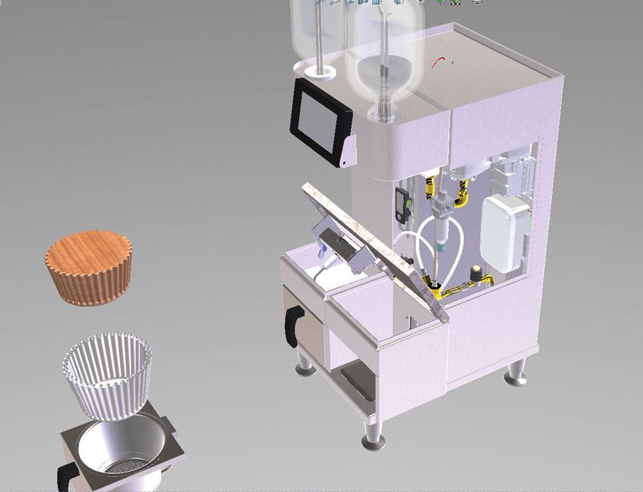
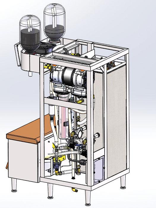
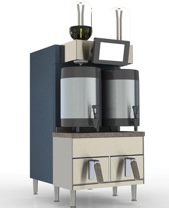
Figure 1
This is the CAD model that was used as a starting point for the DFM project. We’re past the prototype stage. Let’s get ready for batch fabrication.
Disclaimer: This case study of a coffee maker’s sheet metal cabinet features a pair of inventors doing their best to bring a new product to market. The result was an award-winning product design in 2018. Over several years, they gained experience in our fabrication trade, sometimes painfully. It is very brave of them to share this with us.
Editor’s Note: The author’s explorations in design for manufacturability (DFM) are presented as an example of the kind of effort that goes into a DFM project, particularly one involving an industrial design (ID) team that is committed to a vision.
In the previous edition of this column (“A 3-D CAD modeling case study: Using the DFM model to refine the industrial design objectives,” Precision Matters, The FABRICATOR®, September 2018, p. 50), the DFM team was tasked with modeling a method of framing/cabinetry to house the general layout shown in Figure 1.
It is tempting to call this a beginning to our story. To the contrary, this brewer and its related 3-D CAD were evolving for months, as has been documented in this year’s series of columns. At this point, however, the importance of good DFM was about to come to bear with the prototypes having been successfully built and tested. This is where well-informed DFM emerged—not the early efforts that were marred by assumptions and lack of communication. The DFM team understood the constraints covering service covers, weight, and ergonomic goals, and that knowledge revealed itself in 3-D CAD models.
This is why this is a good alternative starting point for the story. The DFM effort really hit its stride and took off. At this point, the 3-D CAD work showed adequately accurate models of the components mounted to the frame. Adequately accurate is appropriate in CAD for items that are purchased off the shelf. Because they are not to be manufactured, only the external details matter. For custom manufactured items, the DFM should model more than just model a blob; the intent is to incorporate the constraints of the fabrication process.
Here’s a CAD tip: Use the save-as tool to save SLDASM as SLDPRT to reduce the CAD overhead for complex models of off-the-shelf components. In this example, the downloaded compressor pump model was extremely detailed. For DFM purposes, it was saved as a part with only the external surfaces. This reduced the rebuild time of the 3-D model considerably.
In this scenario, the DFM team had the option to retain or discard any prior art with regard to cabinetry. Of course, that would have had the team basically starting from scratch, also known as ignoring prior DFM.
To reduce error, marksmen aim small. They sight at a small spot on the bullseye, not just in the general direction of the target. With a similar mindset, the DFM team considered as many constraints as practical to avoid misdirected effort. They decided to aim small.
The goals for DFM on this project included no visible fasteners and an attractive, grained stainless steel appearance suitable for high-end restaurants. Because of the weight of the water tank and compressor pump, the frame had to be fairly robust.
Other important considerations specific to this brewer’s history included a one-off build quantity, a shoe-string budget, and a schedule driven by opportunity.
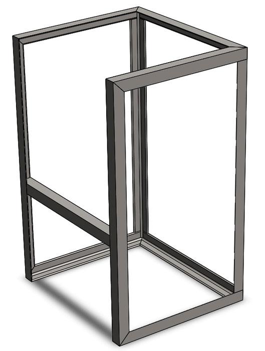
Figure 2
This was the starting point used for a frame to support covers. The objective was to hide the covers’ fasteners from normal line of sight.
This was my first design work involving a coffee brewer. If I knew then what I know now I probably would have started in a different place. The important thing was to start the DFM/CAD modeling work with the idea that the design probably would change, but hopefully not by very much. The best I can say is that this starting point was “edgy.”
Figure 2 shows a starting point. It is a simple box kite-like frame of welded stainless steel that had the shape of traditional angle iron. This simple frame was modeled to allow service access and to accommodate the hanging of covers. It took advantage of the Weldment modeling tool and a simple 3-D sketch, which required just a few minutes of CAD work. Changing the profile of the L angles is an easy CAD edit. It seemed like a brilliant demonstration of speed modeling.
The DFM team’s general plan for assembly was to create mechanical modules bolted to the frame. The frame provided hangers for hooks hidden on the removable covers. Cleverly hidden screws clamped the hooks on the hangers.
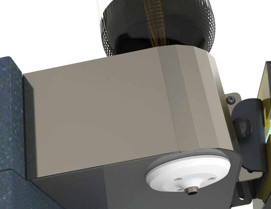
Figure 3 shows an early version of the brew box module. This module inherited considerable detail from prior prototypes. The requirements for mechanical motion, steam control, and aesthetic features were fairly well-detailed.
Eventually, all aspects of the final DFM 3-D model would be fully detailed. However, at the time, there was not time. The next review meeting was looming. Always remember: Detail where it is easy, but in most instances postpone detail in CAD whenever possible.
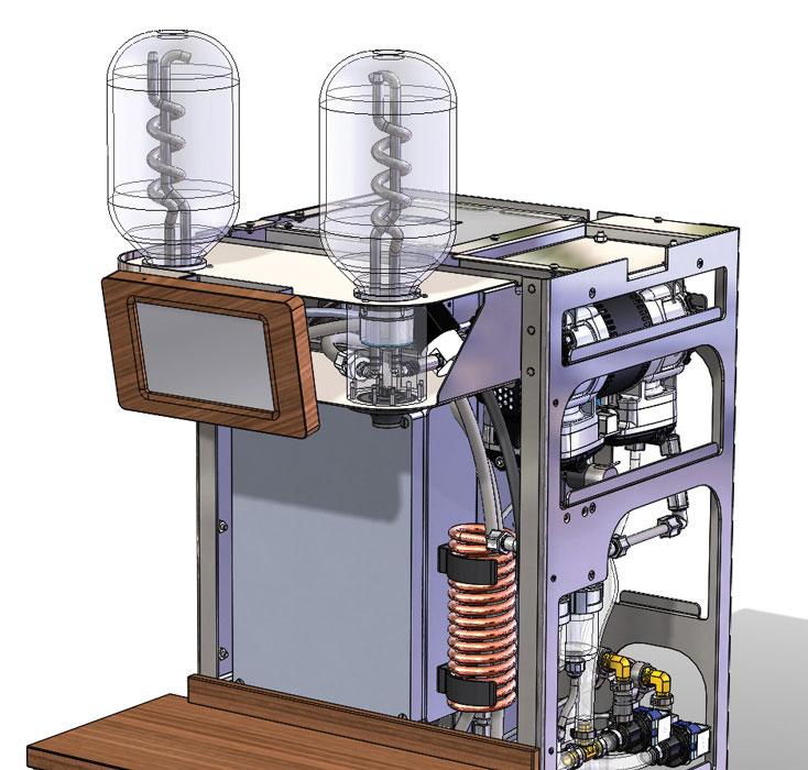
Service access and ventilation were influencers as the DFM work proceeded in detailing the frame. Figure 4 shows more complexity in the weldment as filters and plumbing were mounted inside the frame.
As a constant advisor regarding the level of detail in the modeling, I advocated that the DFM team evaluate the appearance of the seams in the covers. But at this time the DFM team was still in negotiation with ID. The good news was that the DFM team had a very high degree of confidence in the size and general location of required items in the frame.
Even though the box kite frame model was still very crude, it served to provide references for modeling where covers and fasteners had a future. Figure 5 shows a “realistic” rendering of the proposed colors, materials, and finishes. This is an example of one of about a dozen images that were presented to the review committee.
Note this DFM versus ID tip: Model quickly to achieve goals in visualization. Don’t slow down for unneeded detail. In Figure 5, for example, imaginary hooks hold the covers in place. The important detail was the painted lift-off covers, not the stationary grained stainless.
As a guiding principal, the DFM team tried to avoid custom tooling. Figure 6 shows an example of step-bending to form a large radius using common tooling. As with the other realistic images, this was prepared for the meeting so that the ID team had a meaningful visual reference. Step bending as an aesthetic turned out to be soundly rejected and thus helped winnow the potential supplier list.
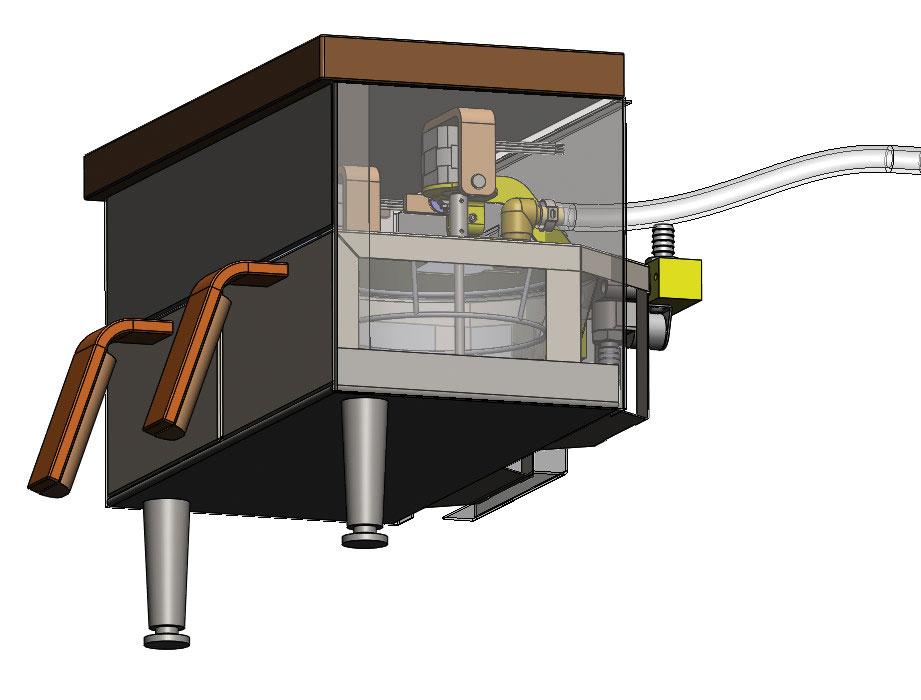
Figure 3
When practical, detail was added to the DFM model. The brew box module inherited (both literally and figuratively) a great deal of design work.
Figure 7 gives a hint about what happened to the box kite frame. The edges that grabbed cover hooks were retained. The rest of the box kite metamorphosed into sheet metal.
The path from Figure 4 to Figure 7 was littered with rejection, confused by revision, and sometimes paved with desperation. DFM can be a lot of fun, too. The story of precision jog bends in 10-gauge stainless, proper installation of fasteners in 304, and blending welds in pregrained stainless is brewing.
Gerald would love for you to send him your comments and questions. You are not alone, and the problems you face often are shared by others. Please send your questions and comments to dand@thefabricator.com.


The Fabricator is North America's leading magazine for the metal forming and fabricating industry. The magazine delivers the news, technical articles, and case histories that enable fabricators to do their jobs more efficiently. The Fabricator has served the industry since 1970.
start your free subscription
Easily access valuable industry resources now with full access to the digital edition of The Fabricator.

Easily access valuable industry resources now with full access to the digital edition of The Welder.

Easily access valuable industry resources now with full access to the digital edition of The Tube and Pipe Journal.

Easily access valuable industry resources now with full access to the digital edition of The Fabricator en Español.
In this episode of The Fabricator Podcast, Caleb Chamberlain, co-founder and CEO of OSH Cut, discusses his company’s...


