


Machine Technology Manager
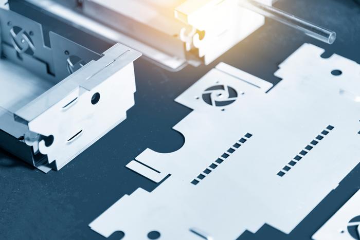
Sheet metal parts full of holes, contours, louvers, extrusions for threaded holes, and other features might be prime candidates for the punch/laser combination machine.
Editor’s Note: The author notes that all machines have issues specific to their manufacturer, model, year, and more. The recommendations that follow should be considered general, and operators should adjust to what works best for their specific machine.
A fabricator usually invests in a punch/laser combination machine for one very compelling reason: to achieve more capabilities in one manufacturing step that doesn’t take up much floor space. A punch/laser machine can cut, form, and sometimes drill and tap all in one work envelope. Automated combo systems can denest and sort too. The machine can use punches for easy-to-punch geometries; form with form tools; laser-cut complex geometries; then denest and sort, all in one setup. It sounds like a panacea.
But there’s a learning curve too, and it’s a little different these days. Years ago many laser programmers started their careers on the punch press and then migrated to the laser. Now that laser cutting dominates, a laser programmer new to the combo machine must adapt to its idiosyncrasies.
Say you’re a top programmer in a shop where the cutting department uses lasers exclusively. Company leadership decides to invest in a punch/laser combination machine and makes you the lead programmer. Where do you start?
Advanced nesting software can account for many of the idiosyncrasies automatically. But as a programmer new to the punch/laser system, you might want to know why exactly the software is choosing to do what it does. You can also be sure that the final programs are the most stable and efficient they can be. The more you know, the better prepared you’ll be.
On the laser, you can nest parts in any orientation. Sure, you might have restrictions dictated by business or job requirements, like putting certain grain restraints on parts. But the laser cutting machine itself has no restrictions on part orientation.
Not so with the punch/laser combo. You need to arrange certain parts on the nest to account for punch tools at fixed angles. Yes, you might incur a material yield penalty, but it’s probably a small price to pay if punching those parts is more efficient than laser cutting them, especially if the right punch shapes and (especially) form tools are available.
Because a laser cutting machine uses slats to support the material, you need to worry about parts falling into the slats and tipping up. You needn’t worry about this on a punch/laser combo machine, which usually supports the material with a solid roller table or brush table.
But you do need to worry about skeletal integrity during cutting, and it has to do with the way the material is handled during the cutting cycle. Most modern laser cutting machines are flying-optic systems in which the cutting head moves and the sheet remains stationary. Conversely, most punch/laser machines move the material during the cutting cycle.
The combo system’s punch usually remains in the same X-Y position during operation while the sheet moves in X—just like a stand-alone punch press. When the combo system’s laser head cuts, depending on the machine, it moves slightly in X and Y, but the sheet itself does most of the moving—again, in the X direction. A gap below the beam allows heat to dissipate and molten metal to evacuate.
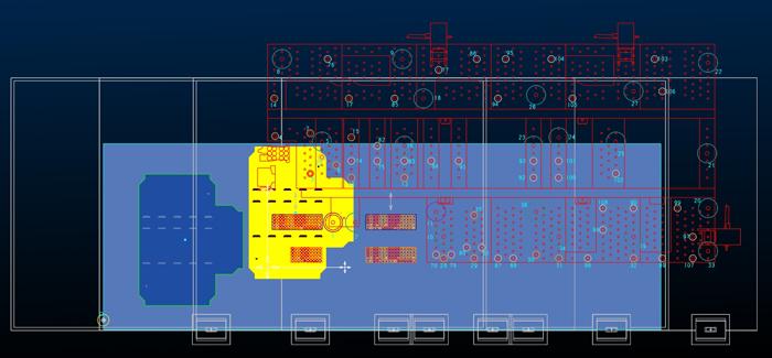
In this application, the unloading device avoids the formed features.
Because the sheet is moving, skeletal integrity matters. It can be affected by program sequence (covered later), part geometry, web width and the number of webs, as well as the material type and thickness. Generally speaking, thin, low-tensile materials have more problems with skeleton integrity than stronger and thicker materials.
Another big factor is a material’s internal stresses. If you’re running, say, galvanneal with a lot of internal stress, cutting can release that stress and wreak havoc on process stability. Say a programmer creates a nest with many long, narrow parts, held in place by microjoints near the end of the program (again, because the sheet is moving). Cutting these long parts releases stress and causes them to bow upward, especially if they aren’t tabbed in the right places. That’s sometimes enough to crash into a processing head. Laser cutting programmers need to deal with this problem too, of course, but combo machine programmers must approach the problem differently because, again, the sheet is moving.
A moving sheet—be it on a stand-alone punch or combo machine—also changes the rules for common-line cutting (CLC). From a business perspective, CLC looks compelling. After all, it’s designed to save time and material. That’s an enticing proposition.
On a punch or combo machine, you again need to consider the skeletal integrity of a moving sheet. If you common-line-cut a number of small parts together, all with a single web around them (like a big picture frame), you now have a big unsupported section with no integrity at all.
Another example: You have four octagons cut along a common line. On a laser, you’re left with a piece of floating scrap in the middle. If the scrap is large and stable enough so it won’t tip, it’s not a problem on a flatbed laser. But on a moving-sheet machine like a combo machine, you need a strategy to manage floating scrap and other unsupported material. Floating scrap is a safety hazard.
You’ll need to adjust your CLC strategy. You might cut with a common line only when it doesn’t leave floating scrap. Or you might perform CLC but with microtabbing to hold the parts and floating scrap in place. In fact, many small CLC parts could be tabbed together with the scrap and then lifted out with part removal automation or sent down a chute as one unit. Of course, this brings up another benefit—and complication—of the combo machine: denesting and sorting.
Many punch/laser combo machines come with some type of in-process part removal, which is a big change from conventional laser cutting where denesting and sorting usually occur manually. Some combos have a chute, which can accept parts of a certain size; others have a mechanized suction device that lifts and removes cut parts. On the surface, these systems appear simple and logical, but from a programming perspective, they introduce lots of complexity.
First of all, the program sequence matters. Consider a part that’s being sent down a chute. If the part goes down the chute in the middle of the cutting cycle, your sheet characteristics will change. A chute-evacuated part will leave an empty space in the nest that needs to be accounted for, lest skeletal integrity problems arise. If the skeleton becomes unstable, you might need to nest with thicker webs and accept a reduced material yield.
These parts need to be able to fall reliably too. If you use a form tool to place a high flange onto a part, that’s great—you’ve eliminated a secondary operation. But to truly save time, you need to make sure the part doesn’t catch on anything as it falls.
For large parts, gravity usually makes chute part evacuation pretty reliable, as long as the chute itself is big enough. But if you’re working with small parts, you might take a different approach. You might laser-cut and punch a group of small parts, leaving microjoints; you’d then use a punch or part ejector to push the small parts down the chute. Because you’re removing many parts consecutively down the chute, the machine spends less time moving a sparse skeleton, which could make the process more stable. After some experience, you might decide that the process is stable enough for a tighter nest (narrower webs) with higher material yield. That said, this is just one hypothetical situation. Your specific part evacuation strategy will depend on your application and company practices.
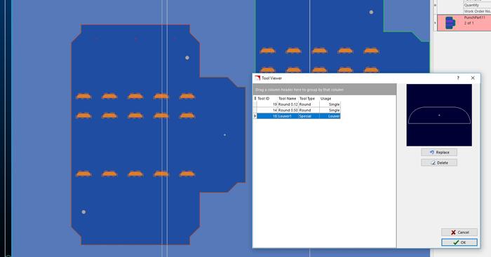
This part takes advantage of the punch/laser combo’s capabilities. It involves laser cutting, punching, and the forming of louvers.
Suction-based part removal systems introduce additional factors. Configured well and accounted for correctly in the nest layout, these removal systems can reduce labor costs significantly. With no human intervention, parts can be cut, lifted out, and sorted for the next operation.
Parts need to be placed on the sheet in an orientation friendly to the unloading device. Depending on your mix of work, these orientation constraints might affect your material yield.
The part characteristics need to allow secure suctioning. In some cases it might not be possible to remove certain parts. Perforation is a prime example. Depending on the hole geometry and density, and the characteristics of the suctioning device, you might not be able to remove a perforated part automatically. One alternative is to redesign the part slightly or add some sacrificial area to create the surface required for secure suction. You’ll waste a little material, but the labor savings you achieve might make this a small price to pay.
The same thing goes for difficult part geometries, like a star shape with narrow points—especially problematic with a new fiber laser that cuts narrow kerfs. These pieces might not release easily from the skeleton. Additional laser cutting techniques might be necessary, like going beyond and looping back around a sharp point. This gives you a clean edge and creates some vacant space to ensure the part has enough clearance to be removed reliably.
The last operation before part removal is especially critical. For a smaller part, the last punch hit might vibrate the material and introduce some skeletal instability, not good for part removal automation. In this case, the punch might cut most of the part. The laser head (which doesn’t contact the part) then makes the final cuts before retracting and making space for the part removal system.
Still, that’s just one example. For other parts it might make sense for punching to be the final operation. It can change from case to case. As long as the part position is stable after the final cut, it’s oriented correctly, and the suctions can work with all the cut and formed features, part removal automation can do its job.
For a laser programmer learning to program a combo machine, the fact that the material is moving is a true game-changer. If you’re new to the punch/laser machine, material movement during the program might be the steepest part of your learning curve.
The material is moving to and fro, and you keep removing pieces from it. You usually want to keep the center of mass moving toward the clamp rail. To do this, you start cutting parts that are the farthest from the clamp rail and then move your way inward. Still, it’s not a hard-and-fast rule. The bottom line is that, when sequencing the program, you always want to be mindful of sheet stability.
Part placement on the nest plays a role here too. Some place larger parts farthest from the clamp rail and smaller parts toward the clamp rail. They then laser-cut and/or punch the large parts first, evacuate them, then end the program sequence by cutting the small parts near the clamping rail.
The thinking goes that small parts have a greater number of web sections in between them, so the remaining skeleton is inherently stronger. Put another way: Smaller parts leave you with more webs, and more webs leaves you with more skeletal strength.
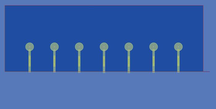
For this part, the punch processed the lollipop shapes, while the laser cut across the punched openings.
Imagine if you were to do the opposite—place large parts near the clamps, small parts away from the clamps, then cut the small parts first followed by the large parts. Remember, the sheet is moving. When you cut large parts at the end, the long and thin web sections have less strength and have the potential to shift, curl, or bend—not a good thing for cutting accuracy or process stability.
Again, your exact sequence will depend on your application requirements and company best practices. You might punch all holes first and then go back and laser-cut the part profiles. This sequence would work fine if the punched holes didn’t remove a lot of mass from the sheet. The sheet would have more than enough mass to remain stable throughout subsequent laser cutting. Conversely, if punching the holes first leaves you with a flimsy skeleton, you’ll affect the accuracy of laser cutting. Again, as long as skeletal integrity is accounted for, the program sequence should work.
Also note that the physical attributes of punching don’t change just because you’ve added a laser to the mix—and this again means that sequencing an operation front to back might not always work. Consider a nest of heavily perforated parts that you fabricate with cluster punches and finish off with laser cutting. Depending on the material and perforation density, you might need to account for distortion that the aggressive perforation creates. This might include punching parts in one quadrant then moving to an opposite quadrant, then back, and so forth.
You might choose to do what’s known as interrupted cutting, where you punch a geometry first and then finish cutting on the same kerf with a complex contour (or another difficult-to-punch shape). But when you’re doing this, you need to make sure the material hasn’t shifted, which again requires a stable skeleton. If you don’t have skeletal integrity, the laser might start in the wrong place—near to but not exactly where the punch left off—and you’ll end up with a bad part.
This brings us back yet again to skeletal stability. Whatever the application on the combo machine, sheet stability rules.
The question used to be straightforward: Punch holes and forms, laser-cut the contours. But these days the laser is so fast that, as a combo machine programmer, you have more flexibility. If you have just the right punch to make a hole, by all means punch it. But if a geometry requires excessive nibbling with a punch tool, laser cutting might be a better choice.
In-process tapping on the combo brings up more options when cutting a hole to be threaded. For thin sheet, you’ll of course still need a form tool to create an extrusion for the threads. If a hole is deep enough to be threaded on its own, you might need to punch it anyway so the tapping tool doesn’t have to make its way through the hardened heat-affected zone of a laser cut. Then again, these days strong tapping tools can make threads in laser-cut holes.
Using form tools on laser-quality parts: Everybody wants it, and it’s one of the most compelling reasons to buy a punch/laser combo. But depending on the specific form tools you’re using, they can introduce their own complications. Most of these are very familiar to anyone who has run a modern punch press with form tools. But if your only experience is in laser cutting, there can be a learning curve.
For example, say you have a large louver close to a laser-cut feature. If you create the louver first, you might not leave enough room for the laser head to perform its cutting. This is why you might choose to perform forming operations as late in the program as you can, before you lose skeletal integrity.
The combo introduces some unique form tool considerations that set it apart even from a stand-alone punching machine. For instance, in classical punching, you’d usually punch all the parts, leave microjoints, then do the forming last. You do risk the microjoints breaking during the forming operation, but if your microtabbing accounts for this risk, then the operation still can be reliable.
But if you have a mechanized part unloader on a punch/laser combo or are using a chute, you can’t perform forming last. You need to cut the part out last so it can be unloaded on-the-fly. You then need to make sure the suction mechanism itself can grasp the formed part.
If you’re evacuating parts via a chute, you might choose to form parts, then perform final cutting to allow the formed part to fall down the chute. The forming occurs late enough in the program that the sheet doesn’t spend a lot of time being moved with high forms, introducing a collision risk; but forming still occurs while the parts themselves are held securely in place along one or multiple edges.
Moving the sheet back and forth in the X direction are a series of clamps at the far end of the table, and that clamping area needs to be considered during programming. Depending on the parts in a job, you might not be able to nest parts efficiently in that area.
The machine’s clamping area can be divided into two elements: (1) the space between the clamps and (2) the space under the clamps. Advanced punch and punch/laser programmers know how to utilize both.
A software’s nesting functions, both for punching and punch/laser operations, can be set to create conservative nest layouts. This gives you greater programming efficiency, because it’s mostly automated. You also might have thicker webs between parts and few or no parts near or under the clamps. It gives you high skeletal integrity, so you’ll have very little chance of error. But you also don’t achieve the highest material yield. This can be ideal for dynamic nest layouts, where you’re nesting on demand. Once the nest layout is made, you’ll never see it again.
But let’s say you have a repeat or blanket order with a consistent, predictable part mix. In this case, it might make sense to create and perfect a static nest—one that runs the same mix of parts arranged in the same place, sheet after sheet. Because the nest doesn’t change, you’ll want to achieve all the material yield you can, while at the same time making the cutting cycle reliable.
It’s a balancing act, and it isn’t easy. For instance, you might choose to common-line-cut certain components, but you do so knowing that once that part is evacuated down a chute, the remaining skeleton (considering the thickness, length, shape, and placement of its web sections) will have the integrity you need to ensure the operation is stable.
After some experience, you might choose to place parts in between the clamps. After even more experience, you might nest parts under the clamps and program a repositioning function. This again adds technical complexity. The sheet cannot move or distort as the clamps reposition themselves; and the area where reclamping occurs needs enough material to ensure the sheet is clamped securely. If not, all parts punched and laser-cut after repositioning could be out of tolerance.
If you have historical job quotes based on laser cutting, they probably aren’t going to be valid for the punch/laser combo. And it’s not just because the two processes have different machine rates.
It comes down to material yield. You might need to deal with lower material yields on the punch/laser when compared to the stand-alone laser machine. This is thanks to part orientation and placement constraints due to fixed punch angles, part removal (via chutes or automation), space needed for clamping, and part placement factors as they relate to skeletal integrity. That lower material yield will influence your part price.
Then again, overall costs will probably be lower, especially if you combine several operations into one. Otherwise, why would you buy the machine in the first place? That said, because of different material yields, combo machines have unique costing characteristics that need to be accounted for when quoting.
The punch/laser system combines the best of both worlds and the challenges of both worlds, along with a few benefits and challenges beyond those of stand-alone machines.
And it starts with programming. Combine good software with solid technique and a solid foundation of process knowledge, and you can mitigate the challenges and accentuate the benefits.
Kevin Keane is SigmaNEST product manager: toolpathing, machine motion, and post processing, at SigmaTEK Systems.


The Fabricator is North America's leading magazine for the metal forming and fabricating industry. The magazine delivers the news, technical articles, and case histories that enable fabricators to do their jobs more efficiently. The Fabricator has served the industry since 1970.
start your free subscription
Easily access valuable industry resources now with full access to the digital edition of The Fabricator.

Easily access valuable industry resources now with full access to the digital edition of The Welder.

Easily access valuable industry resources now with full access to the digital edition of The Tube and Pipe Journal.

Easily access valuable industry resources now with full access to the digital edition of The Fabricator en Español.
In this episode of The Fabricator Podcast, Caleb Chamberlain, co-founder and CEO of OSH Cut, discusses his company’s...


