


Sales Manager
Most modern hydraulic and pneumatic presses have various OSHA-mandated protection systems in place to ensure operator safety. Guards, interlocks, electro-sensitive and opto-electronic devices, emergency-stop devices, and other redundant systems have helped make presses safer for operators than they were in the past.
But when it comes to safeguarding the presses and the dies themselves from expensive damage, the U.S. OSHA standards fall short of their European CEN and Canadian CSA counterparts. The CEN prEN 693 Machine Tools-Safety-Hydraulic Presses states, “Where there is a risk ... from a gravity fall of the slide/ram, a mechanical restraint device, e.g., a scotch, shall be provided to be inserted in the press … On presses with an opening stroke length of more than 500 mm and a depth of table of more than 800 mm, the device shall be permanently fixed and integrated with the press. ”A similar CSA standard (Z142-02) exists in Canada.
For most U.S. press operators, a ratchet bar, locking bolt, or latch is all that’s standing between them and a catastrophic crash if hydraulic or pneumatic pressure is lost suddenly, or if the lifting mechanism breaks. When functioning properly, the ratchet system with a spring latch does an adequate job of arresting the ram’s fall and preventing a catastrophic crash. Unfortunately, the ratchet can show signs of wear that are difficult to detect visually or audibly, even by the most experienced operator. The ratchet and the end of the spring latch can wear to the point where a fall cannot be prevented.
In addition, locking bolts and latches often operate only at the top of the stroke, and ratchet bars at fixed-interval positions. Consequently, the ram often must be retracted to its full stroke position every cycle, even if the part requires only a short opening stroke. This can add considerable, and very expensive, nonproductive time to the cycle.
Safety catchers avert catastrophic crashes and allow the operator to optimize the stroke for any part size.
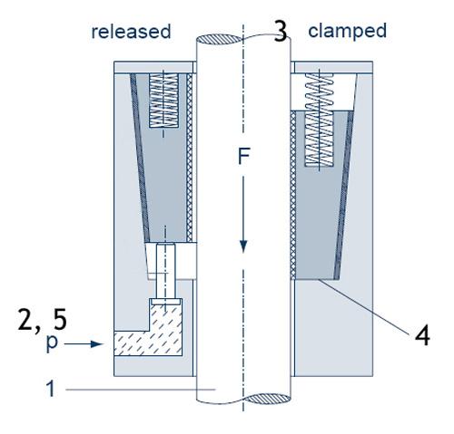
They prevent a load from crashing down at any position of ascent if a hydraulic or pneumatic pressure system fails, or if a rope, chain, belt, or toothed drive breaks (see Figure 1). Therefore, they satisfy the requirements of CEN and CSA safety standards.
A safety catcher has a “self-intensifying” clamp that works a little like the Chinese finger trap you may have played with as a child. Once you put your finger in one end of the paper cylinder, it was very difficult to retract. In fact, the harder you pulled, the more clamping power the simple paper cylinder seemed to exert on your finger. In a similar way, as downward force increases, so too does the safety catcher’s clamping force.
So, if hydraulic or pneumatic system pressure fails, or if a rope, chain, belt, or toothed drive breaks, the safety catcher prevents the load from crashing down at any position of the descent. Here is how it works.
The devices may add cost, but when the cost for a catastrophic press failure is considered—thousands of dollars in downtime, die replacements, or the loss of a customer from falling behind schedule, not to mention the loss of a key operator due to injury—stampers may find them to be a price worth paying.


The Fabricator is North America's leading magazine for the metal forming and fabricating industry. The magazine delivers the news, technical articles, and case histories that enable fabricators to do their jobs more efficiently. The Fabricator has served the industry since 1970.
start your free subscription
Easily access valuable industry resources now with full access to the digital edition of The Fabricator.

Easily access valuable industry resources now with full access to the digital edition of The Welder.

Easily access valuable industry resources now with full access to the digital edition of The Tube and Pipe Journal.

Easily access valuable industry resources now with full access to the digital edition of The Fabricator en Español.
In this episode of The Fabricator Podcast, Caleb Chamberlain, co-founder and CEO of OSH Cut, discusses his company’s...


