


General Manager
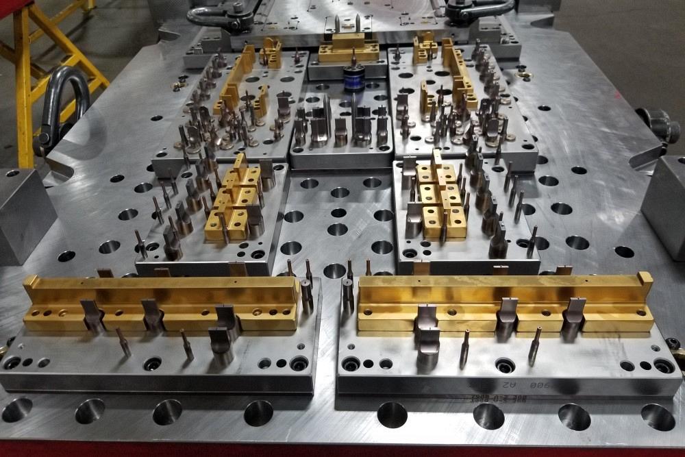
A die for a part for the lighting industry was designed with more than 90 holes and features, as well as numerous bends going the length of the symmetrical part.
The process of stamping parts—from the initial request for quote (RFQ), through the tooling design/build process, and finally, to the stamping production—can be a long and winding road with a large gap between what is designed and what can be manufactured. A part designed with manufacturability in mind will run the smoothest, with the least amount of downtime caused by tooling design-to-production disconnects.
Of course, many parts do not lend themselves to optimal running conditions for a variety of reasons, and a good tooling house knows many methods to overcome such challenges, but those methods typically add cost to the tool and slow the rate at which the tool can run.
That may be fine and well if the costs of the tooling and part production fit the budget of the end user. However, what if the tooling cost pushes that part out of budget or makes the product price noncompetitive? Which features and dimensional criteria that are adding cost to the part may be unnecessarily complex or overdimensioned?
Does the customer company have a tooling expert who reviews part designs to ensure that they are designed with tooling feasibility and cost in mind? Does that expert make sure that tolerances are achievable, and that the tool will run efficiently in production? Subtle differences in how a part is dimensioned can make significant differences in tooling and production cost.
The tooling house rarely knows what a part’s function is. Nor does it know the functions of the features within that part. The tooling manufacturer is entirely dependent on the part print to design and build a production tool that will hold required specifications called out on the part print. While that may be how it should be, technically, if a tooling house knows a feature’s function during the tool tryout process—or better yet at the time of RFQ—that can be highly beneficial in wringing out cost and smoothing an operation.
For example, let’s say a tooling manufacturer is struggling with getting a hole location to check within tolerance on a part because of the inherent nature of the part, combined with a tight block tolerance. After discussing it with the customer, it’s discovered that the hole’s function is simply for hanging the part on a paint line. Had the part designer treated that feature for what it was—a noncritical feature—the part feature tolerance would have reflected that, and it would not have been a problem. The tooling house probably would have been able to quote the project at a lower cost. The tool was likely quoted to account for the difficulty of holding that feature in print, raising the cost of the tool.
Another example of features that can add cost unnecessarily relates to tolerances. A tool house built a large, relatively complex tool for an automotive Tier 1 stamper. The part design had some rather tight profile callouts on some large flanges. The flange tooling designs included a series of step forms going through the part, which was to be stamped from a light-gauge material.
What may appear to be a great design on screen might not be manufacturable in the die. This part’s print had profile tolerances along a tall flange going through a step that gave very little room for error or material variation.
The tooling manufacturer noticed some red flags about some of the part tolerances and callouts. The print had profile tolerances along a tall flange going through a step that gave very little room for error. While a good part could probably be made without too much trouble in tryout, any variation in material condition coming into the tool would spell trouble.
At the time of RFQ, the tooling manufacturer met with its customer team to express concerns about the tolerance and difficult callouts in the part and other parts in the package. The customer team had latitude on tolerance schemes and callouts, but in this case chose not to grant any relief. The toolmaker decided the risk was low; padded the estimate slightly to cover potential problems with the callouts; accepted the order; and proceeded to design, build, and try out the tool.
During die tryout, the tooling house encountered problems with the callouts as anticipated and struggled for weeks to make consistently acceptable parts. It finally produced an acceptable run of parts at its plant, but at a great cost to itself and delays for its customer. The tool house shipped the tool and proceeded to do the home line runoff at the customer’s shop.
Unfortunately, the problem encountered at the tool shop resurfaced in the customer’s press. The heat was on to get the tool to run good parts. The tooling house struggled while attempting to adjust the tool to meet the print at the customer’s plant. After a time, the plant manager stopped at the press to see what was going on.
He looked at the parts and the print. Because he had not been in the RFQ meeting, this was the first time he saw them. He conferred with the upstream manufacturing engineers, who knew the part’s function, and assessed that the tolerance could—and should—be tripled on that feature. The plant manager knew that even if the tool were adjusted to make the part to the original spec, the problem would have occurred again as soon as the next coil was loaded, or even later within that same coil. That would have caused downtime throughout the life of the tool.
As a result of easing the callout tolerance, the home line runoff was off and running.
Obviously, had the customer’s entire team worked with the tooling house at the start, the tool could have been quoted at a lower cost, the toolmaker would have saved money, and the tool could have been delivered on time.
Another example of unnecessarily inflated tool cost plays out in the following. A tool house’s longtime stamping customer asked it to quote a tool for a part that was almost identical to an earlier version. The original part had strengthening embosses throughout and several bends, one of which was a bit challenging. The toolmaker ended up making a custom rocker to get the part to come around at a 90-degree bend. All in all, the tool build went well, and it ran well for the customer.
However, the new version of the part had dissimilar corner radii going around that same corner. One radius was at the base level of the part, and the other radius was at the same level of the emboss. The tool shop recognized this as problematic and asked for a change of that feature to correct the potential problem, but the design was frozen. The tooling house adjusted the quote significantly to allow room for development costs related to that area of concern. Indeed, it turned out to not only be a problem, but it was also a problem that could not be developed away.
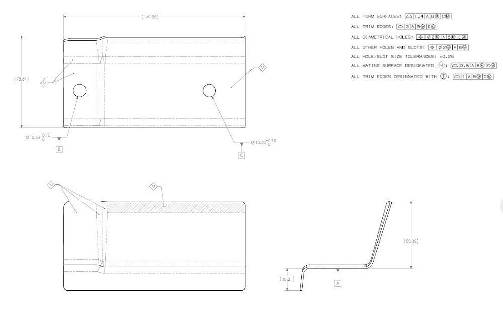
When the part and die were redesigned allowing for triple the tolerance (marked M), the part ran in production without problems.
After weeks of working on the problem, and with trial events looming, the tool house was forced to ask the stamping customer to go to its customer to request concessions on the geometry of that bend to make it manufacturable. The final compromise—essentially equalizing the bend radii—worked for the end customer assembly as well as the physics of the tool.
This feature, which the tooling expert had recognized as problematic and costly, drove up the cost of the tool and nearly delayed critical build events.
Another potential for a manufacturability disconnect is in the part’s bends.
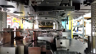
A tooling company built a rather complex progressive tool for a stamper supplying the lighting industry. The part was designed with more than 90 holes and features, as well as numerous bends going the length of the symmetrical part. The tool was quoted per the print without exceptions because although the dimensions were challenging, they were achievable. The tool was designed, built, and the first-off was a relatively nice-looking part.
However, it did not meet some dimensions that spanned from one side of the part to the other, and that presented difficulties. The tolerance did not seem daunting until the sheer number of bends was factored in that influenced the dimensions. Piercing after forming—a preferred method in this situation—was not an option in this case because of press size limitations.
In addition, the tool house had trouble with internal burring on some loops created with shear form punches. After some time and work, it resolved all the issues, had a successful runoff, and shipped the tool. A year or so later the stamper customer asked for a quote on a new version of the part. This time, the quote accounted for the bends and shear loop troubles encountered the first time around.
Revisiting the Design Brings Happy Ending. Sometimes unnecessary costs can be avoided.
Shortly after this higher quote was submitted, the stamper’s customer, an OEM, asked the tooling house for a meeting. The OEM brought its design team and project lead to discuss the part design to explore ways to reduce the die price. The team needed to reduce both the die price and production cost to justify the program life. It solicited suggestions from the tool builder as to how to simplify the part or change the dimensioning to save tooling and production dollars.
The OEM brought out a prototype assembly, explained all the features and their functions, then shared the part print to discuss part dimensioning. Once the tooling manufacturer saw how the part worked as an assembly, it was able to identify immediately the dimensions it struggled with on the previous version of the part that obviously had no bearing on the part performance.
Once the tooling manufacturer learned how a lighting part functioned, it was able to identify the difficult dimensions that had no bearing on part performance and could be removed or relabeled as reference dimensions.
The OEM removed those dimensions or relabeled them as reference dimensions for reference purposes only and not to be reported on.
The group then identified the other troublesome feature—the shear-formed loops. It had assumed that something went into these openings, but as it turned out, they were used simply as a reference locator for an LED board. The tool builder offered up an idea for a more cost-effective way to locate that board, eliminating the troublesome, high-maintenance feature.
The Encore: Combining Parts, Simplifying Shipping. After all this progress on cleaning up the part print’s costly dimensioning, the OEM team asked for an additional design change that would further decrease part cost. It asked if an end cap could be incorporated on each end of the part, which would combine a three-piece assembly into one part. The tooling house did so, garnering huge savings for the OEM, both in not having to tool up the end caps and in assembly time.
Once the tool builder and OEM began down that path, they looked for additional potential savings and found them in the shipping department. The part was designed and built to make the parts more stackable, which translated to significant shipping cost savings.
By meeting for a few hours, focusing on part function, and eliminating or marginalizing nonessential designs, the group found savings of 20% on the previously quoted tool cost, eliminated a mold for the end caps, and saved assembly and shipping costs.
In addition, the stamper running the tool was the recipient of a fine-running tool without the dimensional challenges it experienced with the tool’s predecessor.
Of course, many part designers know the value of well-thought-out dimensioning schemes and how they relate to tooling and production costs. The companies that do not have that expertise tend to overtolerance. In other words, they have too many dimensions that are not needed or unjustifiably tight tolerances on the dimensions.
Perhaps they do this to ensure that their part is not the one to cause fit-up problems in an assembly. Or maybe they leave their software’s default dimension and tolerance scheme at the tightest setting, unknowingly adding difficulty and cost. These are the companies that, without open dialogue with tool shops or stampers with tooling experts, will end up overpaying for their tooling and part production.
In summary, how a part is designed and dimensioned can have a profound effect on the cost of building a tool and even the cost to run that tool. Interaction with tooling experts on part design before obtaining an RFQ for tooling can bridge the gap between concept and production and bring huge savings to product tooling and production cost. Whether that is done with internal experts or with a tool shop willing to spend that time, it is time well spent.
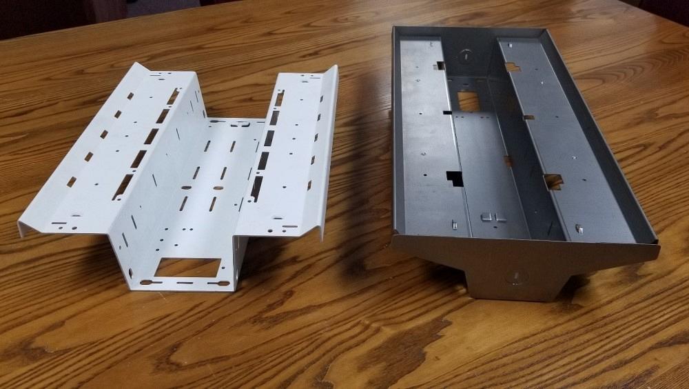
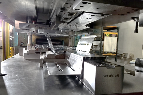
A second round of production of the light fixture part afforded the opportunity to improve the manufacturability of the part and to condense the number of parts from three to one. This light fixture was originally designed to have two plastic end caps. It was redesigned so that the end caps were stamped of metal in the same process, eliminating steps and cost.
1. Excessively tight tolerances on dimensions not critical to part function
2. Geometric dimensioning and tolerancing (GD&T) datum structuring that is not well thought out and often is contradicting
3. Form features that stretch or exceed the physics of the part material
4. Parts that do not have a practical way to be carried through a tool
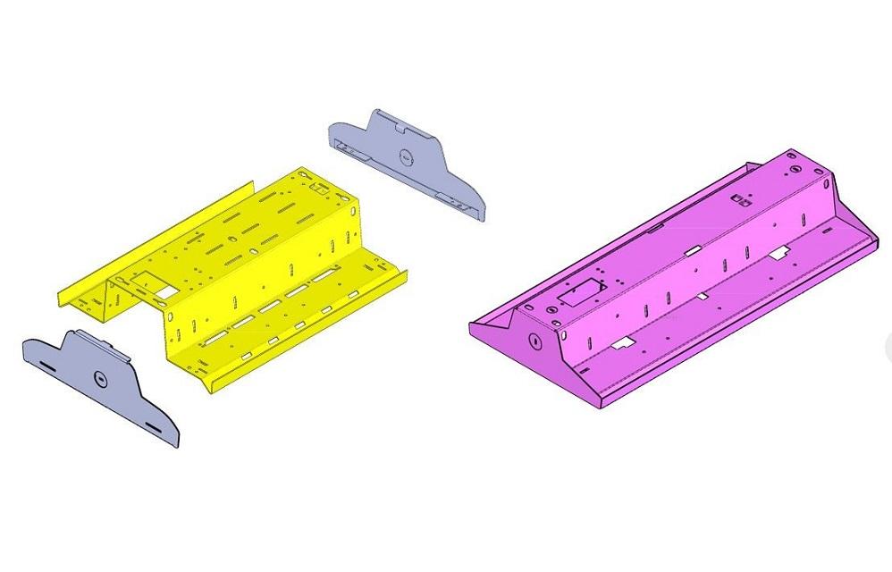
The part was redesigned so that the end caps were stamped of metal in the same process, eliminating steps and cost.


The Fabricator is North America's leading magazine for the metal forming and fabricating industry. The magazine delivers the news, technical articles, and case histories that enable fabricators to do their jobs more efficiently. The Fabricator has served the industry since 1970.
start your free subscription
Easily access valuable industry resources now with full access to the digital edition of The Fabricator.

Easily access valuable industry resources now with full access to the digital edition of The Welder.

Easily access valuable industry resources now with full access to the digital edition of The Tube and Pipe Journal.

Easily access valuable industry resources now with full access to the digital edition of The Fabricator en Español.
In this episode of The Fabricator Podcast, Caleb Chamberlain, co-founder and CEO of OSH Cut, discusses his company’s...


