


Contributing Writer

Perhaps one of the biggest misconceptions about deep drawing is that the metal is stretched into the part geometry. While it’s true that a lot of the parts (including automobile hoods and doors) are made using the process of metal flow and stretch known as stretch drawing, deep drawing, when done correctly, actually involves very little stretch. In fact, the metal thickens through the process of plastic flow. Figure 1 shows examples of deep-drawn products.
This article focuses on the process of “true” drawing, meaning that the product shape is obtained while minimizing stretch.
Have you ever wondered how a very tall vessel such as an oxygen tank is made? How about scuba tanks? Beer kegs? They are made using the deep drawing process.
These particular deep-drawing applications use an engineering concept called draw ratio theory. To understand the draw ratio theory, you must understand one basic metal flow concept: Metal in compression has a great resistance to flow. Because of their resistance, the draw punch must be close enough to the blank edge to minimize the surface area of metal in compression (see Figures 2 and 3 ).
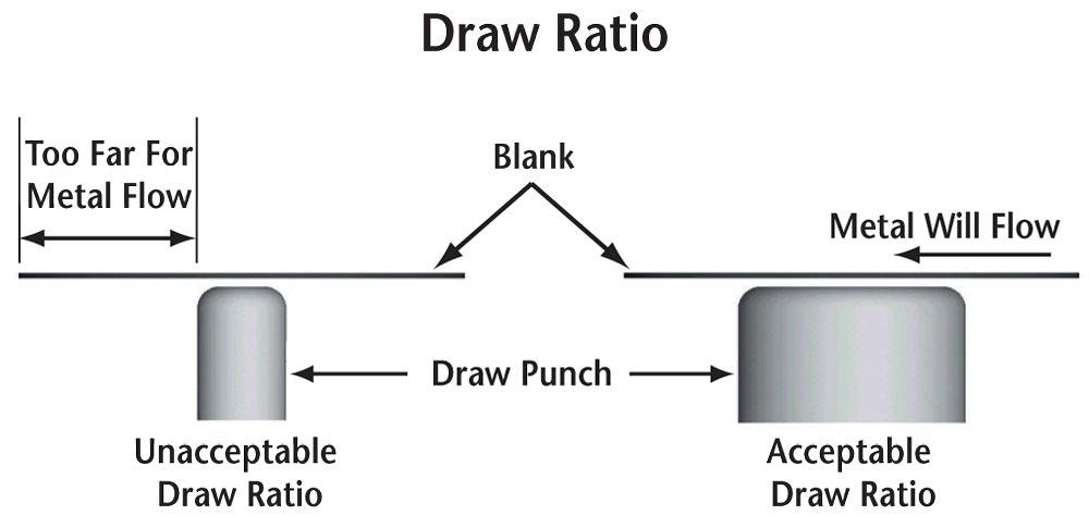
This direct relationship between the draw punch and the blank edge is called the draw ratio. If the draw punch is too far from the blank edge, the metal in compression will not flow, and stretching and possible splitting may result. If the blank is close enough to the punch, the metal will compress and flow inward, resulting in limited stretching and thinning.
The draw ratio is controlled by several basic factors:
Figure 2 shows the basic pattern of metal flow when drawing a simple round cup. Figure 3 shows the relationships between the draw punch and the blank.
Even if the draw ratio is acceptable, a small amount of stretch likely will occur when the metal is impacted by the draw punch radius and the die entry radius. The metal thins because it cannot react to the impact speed of the punch. Slowing down the impact speed reduces the stretching an gives the material time to flow plastically.
Let’s explore the step-by-step process of deep drawing an axial symmetrical round cup out of 0.062-inch material. The cup is 2 in. in diameter and 8 in. tall with no radius on top.
To process a deep-drawn part, you must first know three basic things: the metal thickness, the metal type, and the blank size.
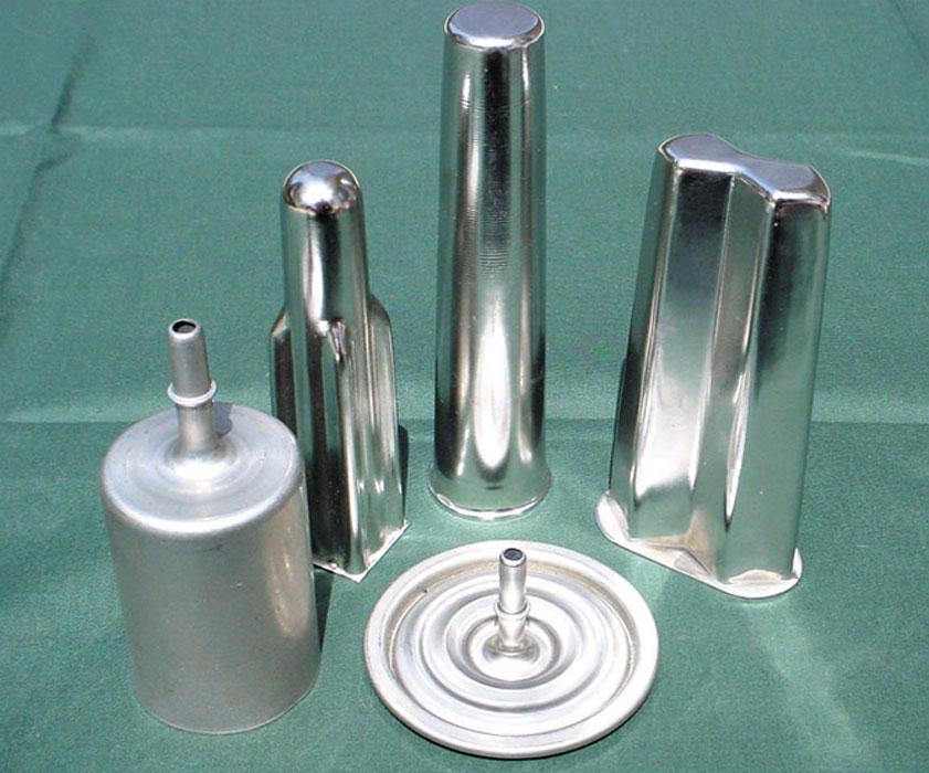
Figure 1
These deep-drawn products shapes were obtained while minimizing stretch.
To calculate the blank size needed for drawing the round cup, calculate the surface area into a flat blank diameter, divide the surface area in square inches by 3.141, or π, and take the square root of the sum. Multiply this number by 2. The formula is:
2√a/π
Surface area= 53.4 sq. in.
Blank size= 8.246
For a cup with a surface area of 53.4 sq.in., the necessary blank diameter is 8.246.
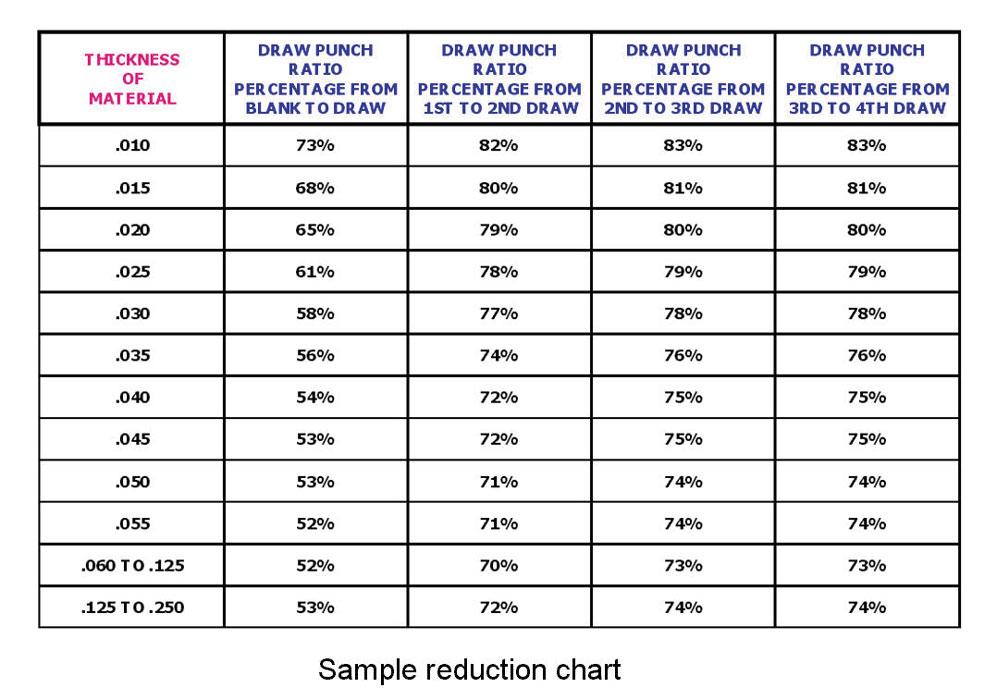
By using a draw reduction chart (see Figure 4 ), you can determine the number of draw reduction percentage for your material thickness. This will give you the minimum size of the draw punch in relationship to the blank size. The punch can be larger, but not smaller.
Begin reducing each draw diameter with respect to the appropriate reduction number:
1st Draw= 8.246 x .52 = 4.288 in.
2nd Draw= 4.288 x .70 = 3.001 in.
3rd Draw= 3.001 x .73 = 2.191 in.
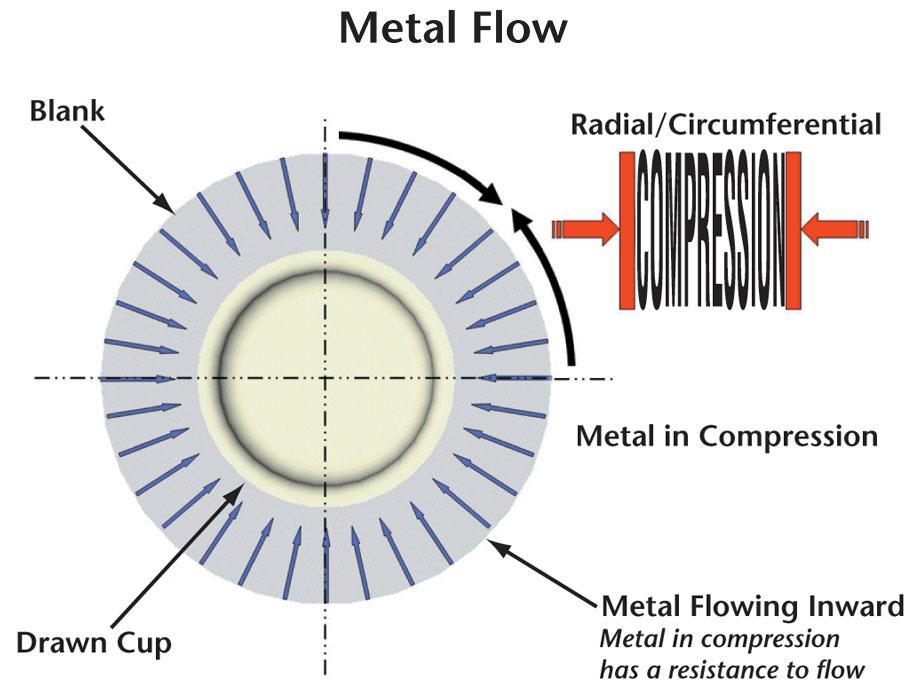
Figure 2
If the draw punch is too far from the blank edge, the metal in compression will not flow, and stretching and possible splitting may result.
4th Draw= 2.191 x .73= 1.599 or 2 in.
Therefore, four draws are required to make the cup.
Until next time… Good luck!


The Fabricator is North America's leading magazine for the metal forming and fabricating industry. The magazine delivers the news, technical articles, and case histories that enable fabricators to do their jobs more efficiently. The Fabricator has served the industry since 1970.
start your free subscription
Easily access valuable industry resources now with full access to the digital edition of The Fabricator.

Easily access valuable industry resources now with full access to the digital edition of The Welder.

Easily access valuable industry resources now with full access to the digital edition of The Tube and Pipe Journal.

Easily access valuable industry resources now with full access to the digital edition of The Fabricator en Español.
In this episode of The Fabricator Podcast, Caleb Chamberlain, co-founder and CEO of OSH Cut, discusses his company’s...


