


Contributing Writer

Numerous factors influence the ability to extrude successfully:
Two of the most influential factors are the fundamental mechanical characteristics of the steel and the die design.
Numerous physical properties of steel affect the ability to extrude. Elongation percentage and n value are the most commonly known, but you must fully understand one unique physical property of steel to understand why the following die deign technique work: When steel is stretched in two opposite directions, it will stretch farther than if it stretches in one direction only. This property is a result of the steel’s microstructure. The key is to deign the die to stretch the material in two different directions.
Another important physical property of steel is that it breaks only in tension and not in compression. For this reason, you should follow tension with compression whenever possible. Cracks called compression fractures are a result of the steel becoming severely brittle when overworked. Even though a crack may be present, it occurred after the steel relaxed in tension.
To prevent problems, try to avoid following compression with tension, because the metal will work-harden and become more brittle when forced into compression, and a loss of ductility and stretchability will result. Later, when you force the metal to stretch in tension, it will be more susceptible to fracturing.
The die design shown in Figure 1 takes into account both of these steel properties. The design can be broken down into several separate components.
Extrusion Punch. Design and build the punch out of premium tool steel or carbide and coat it with a good tool steel coating whenever possible. Grind it perfectly concentric to the pilot and polish it to a mirror-like finish.
Make the radius on the punch about two to three times the metal’s thickness. This radius size is small as compared to a radius used in a conventional drawing die. Be sure to incorporate a pilot point on the punch to locate the pre pierced hole and maintain an even flange height.
Lower (Female) Die. Be sure the matrix is tapered with respect to the natural thinning out of the flange that will occur when it is starched. The clearance between the punch and the die should be about 10 percent less than the metal’s thickness in the flange area.
In other words, uniform ironing should take place along the entire flange length, which can happen only if the die should be about 10 percent less than the metal’s thickness in the flange area.
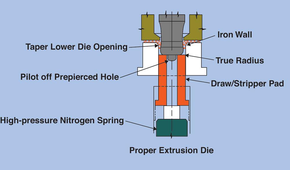
Figure 1
This die design takes advantage of biaxial stretch compression, maximizes flowability, and can be broken down into several separate components.
Internal Stripper Pad. A lot of designers say that the function of the stripper pad is to provide the necessary force to strip or push out the extrusion from the female die. They design it with coil springs and with only enough pressure to remove or strip the extrusion. This works fine as long as you don’t need a long flange or are working with high strength material.
Consider placing a very high-pressure nitrogen cylinder under the stripper and converting it into a high-pressure draw pad instead. This will force the material to flow in a controlled manner rather than just expanding it with a punch, which helps distribute the stretch more evenly throughout the entire flange. It also will force the metal to stretch in two separate and opposite directions, resulting in more stretchability of the material. In addition, the downward force being applied by the draw pad forces the metal to compress slightly.
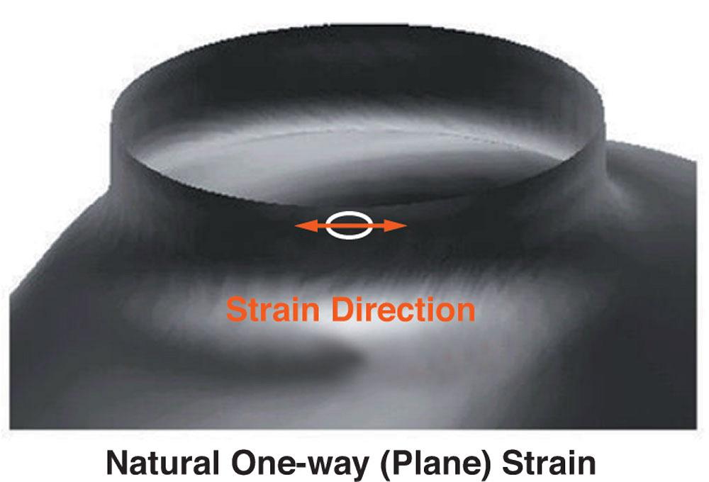
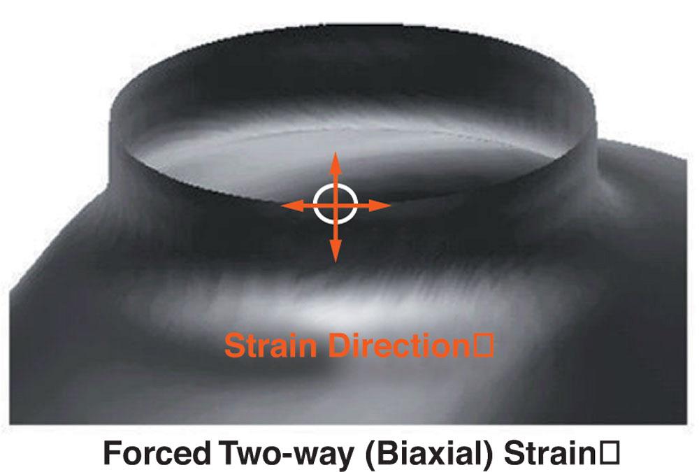
Figure 2 show the strain direction of an extrusion made without stretching with a draw pad. This extrusion is more likely to break than if it were stretched in two separate directions with a high pressure draw pad (see Figure 3 ).
Total Extrusion System. Now think of what is happening during this total process:
Step 1— The steel is clamped tightly between the face of the extruding punch and the high-pressure draw-stripper pad.
Step 2— The metal begins to stretch and flow away from the pilot point in a controlling manner. During this process, the metal is being forced to stretch in two directions—biaxial stretch in one direction because of the natural stretching that is occurring during the hole flanging process and in the opposite direction because of the downward force being put on the metal by the high-pressure drawstripper pad.
Step 3— Just as the metal pulls off the draw pad and stretches near its maximum ability, it is forced into compression by the ironing action of the extrusion punch. The result is maximum stretchability of the material (tension) followed by compression.
The whole concept of taking advantage of material’s properties, along with the process of following tension with compression, can be used to fix a multitude of problems, including those encountered in deep drawing. The key to solving problems with metal is to be able to think like metal. Happy extruding! Best of luck!


The Fabricator is North America's leading magazine for the metal forming and fabricating industry. The magazine delivers the news, technical articles, and case histories that enable fabricators to do their jobs more efficiently. The Fabricator has served the industry since 1970.
start your free subscription
Easily access valuable industry resources now with full access to the digital edition of The Fabricator.

Easily access valuable industry resources now with full access to the digital edition of The Welder.

Easily access valuable industry resources now with full access to the digital edition of The Tube and Pipe Journal.

Easily access valuable industry resources now with full access to the digital edition of The Fabricator en Español.
In this episode of The Fabricator Podcast, Caleb Chamberlain, co-founder and CEO of OSH Cut, discusses his company’s...


