


Professor and Director
Gogiya / iStock / Getty Images Plus
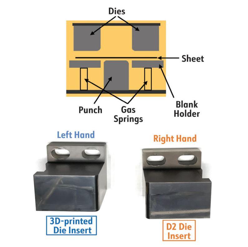
Additive manufacturing is being studied as a method for fabricating stamping dies. The major advantages of using 3D-printed tools in forming applications would be shorter production times for die inserts and lower costs (if complicated geometries require substantial amounts of material to be removed from the initial forged billet stock).
Researchers at Oakland University recently compared 3D-printed forming inserts with inserts that were traditionally machined from D2 tool steel and heat-treated. Both types were coated with IonBond-90 coating. The tools were used to U-bend 1-mm-thick DP980 ultrahigh-strength steel sheet. The researchers formed 50,000 U-bend samples to compare performance of these two configurations.
The objective of the study was to compare the die wear of the coated 3D-printed tools to the die wear of the coated D2 tool steel during room-temperature stamping of the steel sheet. The strip for forming of the U-bend shape was blanked from a 1-mm-thick and 151-mm-wide coil. The depth of draw of the U-bent part was 43.5 mm, and the die entry radius was 5 mm. The design of the progressive die used to stamp these parts has been discussed in previous papers. (“Detecting the onset of galling in stamping of aluminum sheet” and “Die wear of 3D-printed tools when stamping aluminum sheet.”)
Looking at the tool from the end of the stamping line, the D2 insert was positioned on the right side, and the 3D-printed insert was positioned on the left. The blank holder was supported by gas springs charged from a nitrogen tank to predetermined pressure. Figure 1 shows a schematic of the process and the die inserts.
To evaluate the changes on the die surface and surface condition of the U-bent parts, researchers collected samples at the very beginning of the experimental program and after every 1,000 stampings produced, for a total of 51 conditions studied.
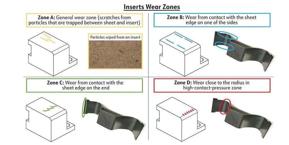
During the experiment, they observed that changes on the surface of the inserts were occurring in different areas (see Figure 2). After 3,000 samples were stamped on the D2 and 3D-printed inserts, scratches started appearing in the general wear zone (zone A), schematically illustrated with yellow lines. A wide scratch also appeared on the 3D-printed insert in the area of contact with the side edge of the sample (zone B), schematically shown with blue lines. Wear from contact with the edge of the strip (zone C) started appearing after 15,000 samples were produced on both the D2 and 3D-printed inserts, illustrated with green lines. In the area of the insert close to the radius (zone D, high-contact-pressure zone), wear started appearing after 20,000 samples were produced on both the D2 and 3D-printed inserts, illustrated with red lines.
On the D2 insert, the number of scratches was gradually increasing until the end of testing at 50,000 samples. A gradual increase in the number of scratches in zone A was observed through the whole experiment on both the D2 and 3D-printed inserts.
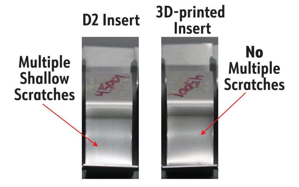
In Figure 3, the sampless surface conditions are compared for the D2 and 3D-printed inserts. For both configurations, samples before 41,001 are in a very good condition. Sample wall surface on the side that was in contact with the D2 insert (zone D) has a gradual increase in shallow, hair-like flow lines, but overall quality of the surface is good. A sample wall surface on the side that was in contact with the 3D-printed insert has a very shallow scratch that appeared at sample 1,001 and remained constant, but the overall quality of the surface is good, and the wall surface does not have an increase in flow lines (or scratches).
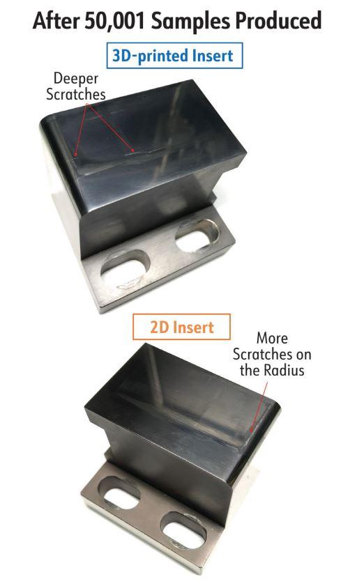
The inserts at the end of the experimental program are shown in Figure 4. The D2 insert had more wear in the area close to the radius (zone D), which resulted in shallow scratches on the samples’ surfaces. Less wear (smaller number of deep and wide scratches) was observed in the general contact zone (zone A, the horizontal surface of the insert). The 3D-printed insert had deeper and wider scratches in the general contact zone, but produced samples had better surface quality, since this insert had less wear in the area close to the radius.
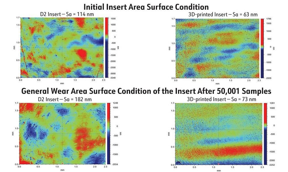
To better understand and quantify the die surface evolution, researchers evaluated the condition of the insert surface using a Bruker profilometer. In Figure 5, the condition of both inserts (the horizontal surface of the insert away from scratches) is shown before testing and after 50,001 samples were produced. No significant change in roughness was observed for both the D2 and 3D-printed inserts.
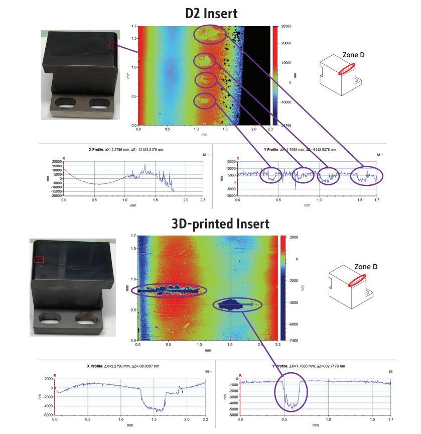
Figure 6 shows the condition of both inserts after 50,001 samples. Wide scratches are visible on the surface of the D2 insert, approximately 0.1 mm wide and 0.005 mm deep in the area close to the radius (zone D). Very few wide scratches are visible on the surface of the 3D-printed insert, approximately 0.18 mm wide and 0.005 mm deep in the area close to the radius (zone D). Since there are only a few of those scratches, they do not decrease sample surface quality.
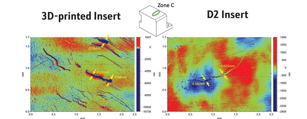
In Figure 7, the condition of the 3D-printed insert after 50,001 samples in zone C is compared to the condition of the D2 insert after 50,001 samples were produced. The 3D-printed inserts show scratches 0.03 to 0.08 mm wide and up to 0.003 mm deep in this location. More narrow and shallow scratches—about 0.025 to 0.06 mm wide and 0.001 mm deep—were observed on the D2 inserts in zone C.
This research project was funded in part by the Auto/Steel Partnership with contributions from Ionbond LLC, which performed coatings of tested inserts, and Sun Steel Treating Inc., which provided heat treatment for the inserts.

Professor and Director
Oakland University Center of Advanced Manufacturing and Materials (CAMM)


The Fabricator is North America's leading magazine for the metal forming and fabricating industry. The magazine delivers the news, technical articles, and case histories that enable fabricators to do their jobs more efficiently. The Fabricator has served the industry since 1970.
start your free subscription
Easily access valuable industry resources now with full access to the digital edition of The Fabricator.

Easily access valuable industry resources now with full access to the digital edition of The Welder.

Easily access valuable industry resources now with full access to the digital edition of The Tube and Pipe Journal.

Easily access valuable industry resources now with full access to the digital edition of The Fabricator en Español.
In this episode of The Fabricator Podcast, Caleb Chamberlain, co-founder and CEO of OSH Cut, discusses his company’s...


