


Troubleshooting quick die change in stamping operations
How to avoid getting blindsided by gap jumping, stripping force, cycle speed, and future-proofing

When installing a quick die change system, you should be armed with knowledge about potential problems to avoid gap jumping, stripping force, cycle speed, and future-proofing. Getty Images
Even for those with experience implementing quick die change (QDC), unexpected problems occur and unfamiliar details need attending to that could have a major impact on QDC system performance.
Being armed with knowledge about potential problems can help you avoid getting blindsided by them. Doing so helps to keep employees safe and solidify a good return on investment (ROI).
Conversely, failing to account for the unexpected can result in a lift capacity shortfall, a sudden need for additional equipment, increased risk to personnel, and suboptimal ROI. Two of the key benefits to QDC, beyond the obvious speed benefits of single minute exchange of die (SMED), are increased personnel safety and reduced risk to dies during die handling.
To be ready for potential problems, you should have a few important items on your checklist when reviewing QDC applications: gap jumping, stripping force, cycle speed, and future-proofing. This is also a great time to improve the overall process and implement safety improvements. These often are overlooked in the initial project scope.
Gap Jumping
Sometimes a die hangs over a gap. One die change failure can occur when you don’t take the gap into account. Can you remove the die across the gap? How big can the gap be?
In an ideal arrangement, bolster extensions or prerollers are used to provide a tight transition for moving the die from the bolster surface to supports outside the press with ample room to safely remove the die (see Figure 1). Alternative methods such as die carts or die tables are sometimes available. Bolster extensions typically are installed with die lifters in the press for a near-zero gap between lifters and extensions.
However, if the press bed or something else extends out into the loading area, causing interference, you may want to have a gap between the lifters and the external support. Then the die must do what’s called “jump the gap.”
Three to 6 inches or even a foot of gap may seem small relative to the size of the stamping press. Furthermore, it may seem logical that a die should be able to hang off the bolster a few inches to jump the gap. However, the underlying supports, such as die lifters, often are sized with assumptions that are no longer valid for this condition. Die lifters provide support only for that portion of the die that is balanced under its center of gravity. If you did not calculate for gap jumping when sizing the lifters, they may be undersized for the gap requirements.
In physical terms, weight outside the lifter envelope dramatically shifts the amount of weight and location of the die’s center of mass relative to the lifters. Essentially, the amount of lost lift force is equal to two times the gap distance multiplied by the lift force density. So, a 1-ft. gap is really like a 2-ft. gap in terms of lost lift force.
With an overhang and undersized lifters, as the die moves and lifters attempt to support the die, the lift force is inadequate, and the die lifters collapse near the edge. This causes a loss of control of the die transition. As a result, die dragging, unevenness, and damage to lifters and external die cart will occur.
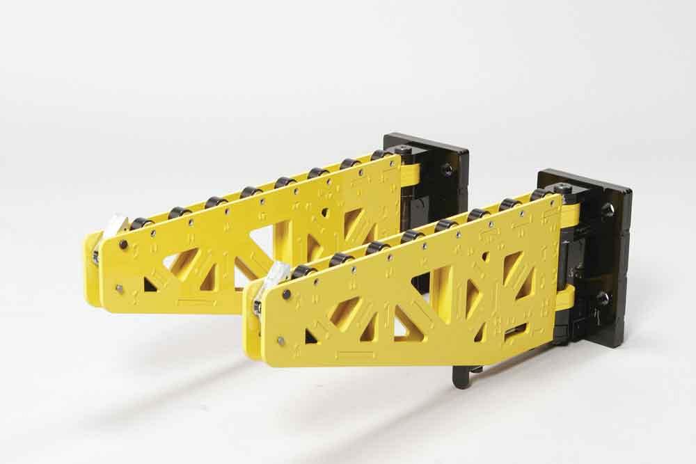
Figure 1
The size of bolster extensions that you use must be engineered to support the weight of the die over the gap. Courtesy of PFA Inc., Germantown, Wis.
You can prevent this by planning properly for the gap. Minimize the gap between die lifters and supports. This ensures that die lifters reach the bolster’s edge on the side designated for die loading and unloading. Be mindful that die rollers and die lifters that do not reach the edge are equivalent to a gap.
When you calculate the lift force density required from the die lifting system, subtract two times the gap from the die length. It’s best to discuss increasing lifting capacity to accommodate gap jumping with your QDC system provider.
Cycle Speed, Dynamic Force
Is die weight the only factor in play when applying clamps to the die? To right-size the clamping system, you must consider both weight and dynamic force.
When you calculate how much clamping force is needed to hold a stamping die in the press, you might measure only the die’s weight. For many dies that run at moderate cycle speeds, the additional forces that develop as the upper die half accelerates upward may be relatively low and within an already established safety margin. On the other hand, it would be helpful to know the real weight of the die under movement, or dynamic weight. So what is the real dynamic weight of the die?
Imagine the familiar analogy to the fast acceleration of a car or a rocket launch. When a rocket launches, the constant force of lift is an acceleration adding to the force of gravity, as if gravity is multiplied in the downward direction. Standard gravity is 1G (32 ft./sec.2). If a die is accelerated upward from bottom dead center (BDC) (approximate sinusoidal movement), the total effective force or equivalent dynamic weight for the upper die would be the normal weight 1G plus the additional dynamic force.
Figure 2 shows the combination of static and dynamic loading to create a dynamic weight factor (DWF). This is the number of G’s that the upper die undergoes during peak acceleration. Thus, the dynamic die weight (upper die scale weight x DWF) is the minimum real weight that must be clamped to prevent the overload of a clamping system on the upper die.
To resolve the real weight challenge, it’s important to understand the unique aspects of the press and calculate for acceleration.
Note that for strokes per minute (SPM) less than 100 and opening height less than 12 in., the dynamic weight is less than three times the scale weight. So, based on weight alone, a die could be clamped at a typical 4-to-1 ratio and have a 1G margin to spare, so to speak. With a servo-driven press, the control adds significant ability to stop and start movement quickly, which for calculation purposes is greater than for typical acceleration.
While a servo is beneficial in terms of faster SPM and better control, the added demand on clamping systems should be factored into the selection process. In this case, reducing the opening height may not reduce the peak acceleration, so caution is advised. Discuss this with your press manufacturer and advise your QDC system provider of any unique demands on the clamping system.
Stripping Force
You know you sometimes have to account for stripping force in clamp sizing, but by how much? How do you calculate it?
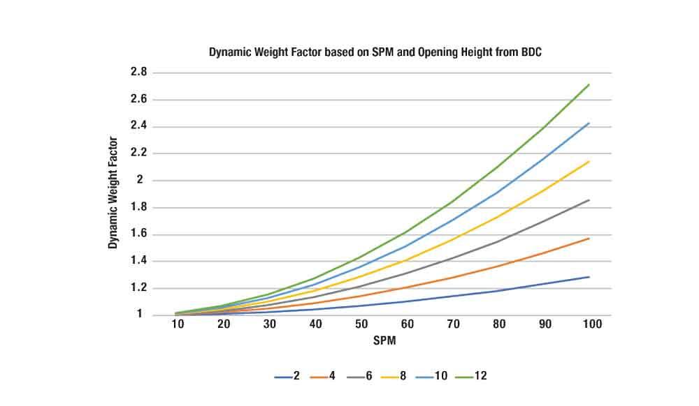
Figure 2
You can calculate the die’s upper half dynamic weight by multiplying the dynamic weight factor by the upper die weight. Courtesy of Mark Scanlan.
Just as speed affects clamping, so can the similar impact of stripping forces. In general, the clamping force is the amount of force needed to secure the upper and lower die halves to the press plates, within some expected safety margin. While dynamic load affects clamping of the upper die half only, stripping forces affect both the upper and lower clamps.
Friction causes a stickiness that makes the die halves stick together. Stripping force is the force required to separate the die halves caused by that friction. If the force is not applied internally to the die with springs, it is applied by the press when it opens. At the upper limit, opening force could be as high as the press opening tonnage, as if the die halves were welded together.
Typically, maximum tonnage opening would be an extreme case; however, if the stripping force has not been estimated in advance, such conditions could develop unexpectedly. The general rule for stripping force seems to be that it is about 10 to 30 percent of the cutting force. Therefore, the additional force needed to facilitate stripping should not exceed about 30 percent of press tonnage.
As the stripping force resists the opening of the die, all clamps feel this force. When you are calculating clamp requirements, you should add the stripping force to the dynamic loading force. Lower clamps would experience this force minus the die weight. As a result, the quantity of lower clamps needed tends to be fewer than are needed on the upper clamps on dies with high speeds and high stripping forces.
To counter potential problems related to the stripping force, size clamps properly according to the cutting and stripping forces.
Each plant should have a safety program and safety manager to provide company policy on equipment margins of safety per national and local standards. Most applications are reviewed for die weight as the most significant factor, but stripping force also is part of the equation. It is essential to apply the correct factor of safety to the application. Know which dies are atypical and what drives the stripping force so that unique cases can be identified and proper precautions taken.
Double-check if the stripping force applies for each die reviewed for QDC and confirm that the systems are adequate for the dies. It’s advisable to share this information with your QDC systems provider.
Future-Proofing
When determining your QDC system, it’s important to plan for future projects that may obsolete your equipment. What other dies might run with the new QDC system today? Tomorrow? How big will your dies be in the future? What are your potential future projects?
Knowing all your die weights, loading methods for gaps, dynamic loads, and stripping forces will be helpful in determining minimum requirements for clamps and lifters. The question that often gets forgotten is, Which dies will we need to be running in the future?
It is likely that the part types have some consistency. With a little effort to think into the future, you might be able to predict what the largest, heaviest, and fastest die will be within a year or two of adding a new QDC system. Often the most important jobs with highest change frequency will gravitate toward the new system installation, regardless of initial planning before system implementation.
Purchasing slightly larger clamps or stronger die lifters does not add appreciably to the overall system cost, especially if that negates the need to change the equipment later. Throwing away good components to install higher-capacity components later (die lifters, for example) can be very costly and would reduce the ROI. Spending a little more on system components today is often a smart choice.
Think about making your system modular. Are there ways to select die lifters to add more if needed? Can more clamps be added incrementally? Discuss the possibilities with your QDC system provider and request multiple options for your application.
Also, consider that upgrading the QDC system beyond current needs can be a safety enhancer as well. The QDC system is a great tie-in to other safety devices, such as barrier protection. You may have opportunities to combine it with other lean manufacturing and safety initiatives for lower overall cost of implementation and improved efficiency.
When defining the scope of the project, consider the unexpected and, where possible, check for the unique aspects of each application. That way, you’ll have a better chance of getting it right the first time and, hopefully, avoid being blindsided by problems.
Mark Scanlan is vice president and general manager for PFA Inc., N118 W18251 Bunsen Drive,Germantown, WI 53022, 262-250-4410, mscanlan@pfa-inc.com, pfa-inc.com.
About the Author
About the Publication

subscribe now

The Fabricator is North America's leading magazine for the metal forming and fabricating industry. The magazine delivers the news, technical articles, and case histories that enable fabricators to do their jobs more efficiently. The Fabricator has served the industry since 1970.
start your free subscription- Stay connected from anywhere

Easily access valuable industry resources now with full access to the digital edition of The Fabricator.

Easily access valuable industry resources now with full access to the digital edition of The Welder.

Easily access valuable industry resources now with full access to the digital edition of The Tube and Pipe Journal.

Easily access valuable industry resources now with full access to the digital edition of The Fabricator en Español.
- Podcasting

In this episode of The Fabricator Podcast, Caleb Chamberlain, co-founder and CEO of OSH Cut, discusses his company’s...


