


Senior Editor
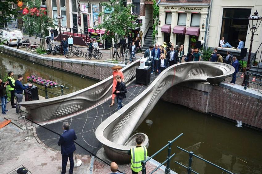
Walking across a canal in Amsterdam’s city center, Queen Maxima of The Netherlands opens the first metal 3D-printed bridge in the world in July 2021. MX3D/ Adriaande Groot
Imagine the structural fabrication operation of the future. Automation dominates the shop, with beam processing lines integrated with conveyors that feed downstream operations, including robotic welding.
Apart from robotic welding, though, you see another robot that’s not laying down welds—at least not in the traditional sense. It’s a wire-arc additive manufacturing (WAAM) process, a directed energy deposition (DED) additive manufacturing technology. And it’s not producing traditional beams and plates. Instead, it’s producing unique connectors and components that, when integrated amid traditional steel elements, optimizes the integrity, functionality, safety, and durability of a structure. In this future, additive manufacturing has found a home at the structural fabricator.
Leroy Gardner shares a similar vision. “Additive manufacturing is likely to complement rather than replace the conventional production.”
Gardner made this comment during the 2021 NASCC: Steel Conference, organized by the American Institute of Steel Construction. He added that the statement still applies today.
Gardner is a professor at Imperial College London. Working with The Alan Turing Institute, he and his research team collaborated with a Dutch company called MX3D, whose WAAM process built the first metal 3D-printed bridge in the world. Other collaborators included the design firm Arup and the Dutch design studio Joris Laarman Lab. (Managers of the latter founded MX3D as an independent company in 2014.)
Opened in July 2021, the pedestrian structure now spans over a canal in Amsterdam. Save for the decking, all of it was fabricated by depositing layer after layer of 308LSi austenitic stainless steel welding wire. Strategically placed gauges will monitor the structure’s performance throughout its life.
Such testing and monitoring should help build the scientific and engineering foundation needed if AM is to gain a footing in the construction business. Structural fabricators and other industry stakeholders need established methods of testing, measurement, and fabrication to ensure structures are safe and durable. The challenges are real but—as work on that first 3D-printed metal bridge has shown—not insurmountable.
Most who have seen metal 3D printing systems in action immediately see their benefit in certain industries, especially in medical and aerospace arenas. “The aerospace and biomedical industries have been the first to take up the technology,” Gardner said. “In aerospace, lighter weight and more geometrical refinement are well rewarded. In bioengineering, compatibility and customization are critical.”
But what about the construction industry? Those experienced in structural fabrication might see metal additive manufacturing as a bit far-fetched, especially from a cost standpoint. Hot-rolled beam and plate production is proven and cost-effective. How could systems that deposit metal layer by layer possibly compete?
“It’s true that technology uptake in construction is slower than in other industries,” Gardner said, “but we’re already seeing some early examples of some applications.”
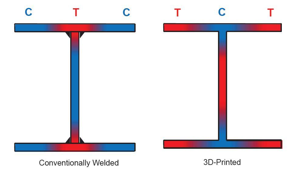
FIGURE 1. Beams that incorporate 3D-printed flange tips could leave those areas in residual tension (as shown on the right), which could enhance their performance. Leroy Gardner
For instance, Gardner described some lighting nodes for hollow structural sections (HSS) 3D-printed in a web-like, almost organic-looking shape. He also described aluminum façade nodes, 3D-printed in odd geometries. Each was designed to optimize strength, performance, and even lower the cost of assembly. Like in other sectors AM serves, the true cost savings isn’t in the part costs but in the cost savings those optimized part designs create.
Gardner cited research that used powder bed fusion techniques to create corrugated, wavy shell tube sections. The tubes look utterly foreign, but they tout some eyebrow-raising performance characteristics. As Gardner explained, “It turns out that shells [tubular sections] with corrugations increased load-carrying capacity and reduced imperfection sensitivity.” Even tested under heavy load, those wavy sections of tubing stood strong.
AM even has potential for conventional I-beams, especially when it comes to residual stresses. As Gardner explained, residual stresses typically have a negative effect because of where compression and tension reside on a conventionally welded I-beam profile. Tension resides in the flanges, just above and below the web section, right near the welds. This leaves the flange tips of the I-beam under compression. But what if those flange tips were 3D-printed (see Figure 1)?
“Printing flange tips last leaves them in residual tension,” Gardner said, “which enhances minor-axis buckling resistance.”
The potential of AM seems transformational. Material properties could be customized to exhibit certain characteristics—like strength, hardness, ductility—in certain areas of each structural component. AM could give architects ultimate design freedom, and each element of the steel structure could be optimized for maximum utility.
One early concept of the 3D-printed bridge even involved mobile robots that would lay down metal and additively build on-site, though that was scrapped due to logistics and safety concerns. As fabricators know, it’s easier to work in the controllable environment of the shop rather than in the field, and the same applies to AM—though the idea of “building” on-site, precise layer after precise layer, would bring yet another level of efficiency. Just imagine arriving to the job site with spools of welding wire instead of truckloads of unwieldy beams and plates.
“Within our facility, we actually put the robots on the bridge and had them print itself, so to speak,” said MX3D CEO Gijs van der Velden.
It all sounds amazing, which is why research and development continues. Much of that research focuses on material testing. After all, the performance of hot-rolled steel has decades of data behind it. Additively manufactured metal, not so much.
“After experimenting with [WAAM], we concluded that this was a discovery that needed to be scaled up, and we built MX3D around it.”
That again was van der Velden of MX3D. From the beginning, MX3D remained open about its technological development. It posted videos of WAAM producing a few smaller metal parts, and before long, several large companies—including Air Liquide, ArcelorMittal, and Autodesk—reached out about supporting a larger project that could prove WAAM technology could indeed produce larger components.
MX3D’s WAAM process printed the bridge over a period of six months in 2018. MX3D
“Being in Amsterdam, we thought that printing a bridge would be symbolic,” van der Velden said. “If you see a bridge in the city center, you know this technology has been approved by the city council to be reliable and safe.” He added that Gardner at Imperial College (and, soon after, the Turing Institute) got involved through the Lloyd’s Register Foundation, a funding partner for the project.
MX3D printed the bridge over a period of six months in 2018. Project collaborators chose MX3D’s WAAM process for several key reasons. First, compared to all the AM variants in use, WAAM has very high deposition rates, depositing up to about 10 kg of welding wire per hour, per robot. The fact it relies on welding wire—a proven product with established chemistries—is another plus. In many ways, the technology is a kind of adaptive gas metal arc welding. Think of it as weld cladding taken to its logical extreme, with layer after layer shaping into an entirely new fabricated product.
“We work with off-the-shelf wire and off-the-shelf gas,” van der Velden said. “The new technology involves the control and the [software] required to stack these 3D geometries. There are thousands of individual coding lines to do this. Normally, a welding robot does one thing a million times. Now, it deposits millions of layers, and every layer is something new. We measure the interpass temperature, and for [weld shrinkage], we now know what geometries work well for WAAM. Generally speaking, flat plate is very difficult to print, because there will be distortion effects. But if you have a pipe, a cylindrical form, or various other geometries, the distortion can be contained by the form itself.”
Designers can always change a component’s shape to optimize the process. Within and outside the structural space, design freedom—tailoring the variables for the application at hand—is one of AM’s greatest selling points.
Using AM to build a bridge is uncharted territory, especially considering that engineers really didn’t know how printed metal would perform and, most critically, how it would fail. Here, Gardner and his team headed out to chart some new territory.
The team tested the material itself and the performance of printed metal components. They also performed full load testing on the entire bridge. To test the material, they worked with typical tensile coupons cut from 3D-printed metal sheet. Some coupons ran parallel to the welding direction (0 degree), others ran perpendicular to the weld (90 degrees), and still others ran diagonally (45 degrees).
The team relied on a digital image correlation (DIC) system, a noncontact technology with a special camera that, at regular intervals, took images of the material undergoing a tensile test. It then recorded the shifts in the grain structure. They tested coupons in both machined (smooth surface) and as-built (wavy surface) conditions.
The details they uncovered helped build an engineering foundation for structural components fabricated with WAAM, which they then used as a basis for finite element simulations. Among other details the team discovered was the material’s unusual behavior under tensile tests. The team found that, due to heat effects from the weld process, the metal’s grains were arranged in such a way that they performed better in coupons where the weld direction ran 45 degrees to the pull test.
“We wondered why we got this lower stiffness in the 90- and 0-degree directions, yet higher in the 45-degree directions,” Gardner said. “We spoke to our friends in material science, and they weren’t surprised. It relates to the temperature and thermal gradients created during the process.”
Specifically, it has to do with the orientation of crystals in the metal. Random orientation means you can pull the material in different directions and get similar results. The WAAM-created metal, however, had crystals that were preferentially orientated in the direction of the thermal gradient. “More crystals were aligned vertically than in any other direction,” Gardner said. This meant that “when you pull the material at 45 degrees [to the weld direction], you’re pulling the unit cells across the diagonal. And steel is stiffest in that cross-diagonal direction.”
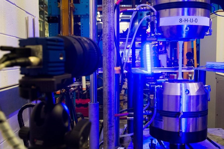
This digital image correlation system photographed pull-tested WAAM coupons at regular intervals. Leroy Gardner
Another key finding at the material level: The as-built sections (that is, those with undulating or wavy surfaces from the AM process) had material property performance that was only about 20% lower than AM material that was machined to a smooth surface. That’s a manageable difference engineers can account for. If the WAAM process required secondary machining for components to be usable and safe, the economics behind the technology would change considerably.
As Gardner put it, “In general, it was encouraging to find mechanical properties [of AM material] that weren’t so different from what we normally see, even with the undulations [the layers of weld metal making up the material surface].”
On the component level, measurement presented some challenge since the WAAM-fabricated pieces had, in their unmachined form, bumpy and irregular surfaces—not good for calipers or other conventional measurement tools.
To measure them properly, the team relied on a laser scanner and, for the inside diameter (ID) of tubular sections, created a silicon casting mold of the ID. They pushed the castings out of the tube, scanned that casting, and joined the inner and outer scan to get a full picture of the tested specimens.
“This was really useful,” Gardner said, “because we could now measure how much geometric variability you get, where the weak points were, and other statistics about the geometric properties of these components.”
In subsequent compression tests, the team found that buckling occurred in a predictable way, where the material surface had the most imperfections—a positive sign, Gardner said, considering that in conventional material, buckling tends to occur in random, hard-to-predict ways. “We were able to correlate the laser scans with the failure modes.”
With all these tests, researchers found that as-built (undulating surface) components performed similarly to conventionally produced material, “provided you take into account the weakening effects of the undulations,” Gardner said. That significant finding will likely form an engineering bedrock for future development. Gardner also compared the results to the AISC code for stainless steel (AISC 370) and found that the material’s behavior was predictable and generally in line with the standard. That’s another critical finding. After all, if the material’s behavior wasn’t predictable, it wouldn’t meet construction industry standards and, hence, wouldn’t have much use in structural fabrication.
From there, the team tested the entire bridge, applying horizontal loading with jacks, pushing the handrails in and out, and vertical loading with large water tanks and concrete blocks. The bridge performed well and, most critically, behaved similarly to the finite element simulations the team built, based on findings from tests at the material and component levels.
In October 2018, the bridge was unveiled to the public during Dutch Design Week, where crowds walked across it, admired the design, and witnessed one vision of bridge construction for the future.
The team performed further load testing and found the bridge performance again matched the performance predicted in the finite element model—another good sign.
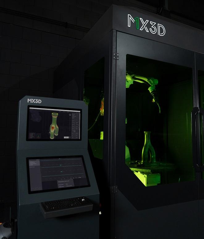
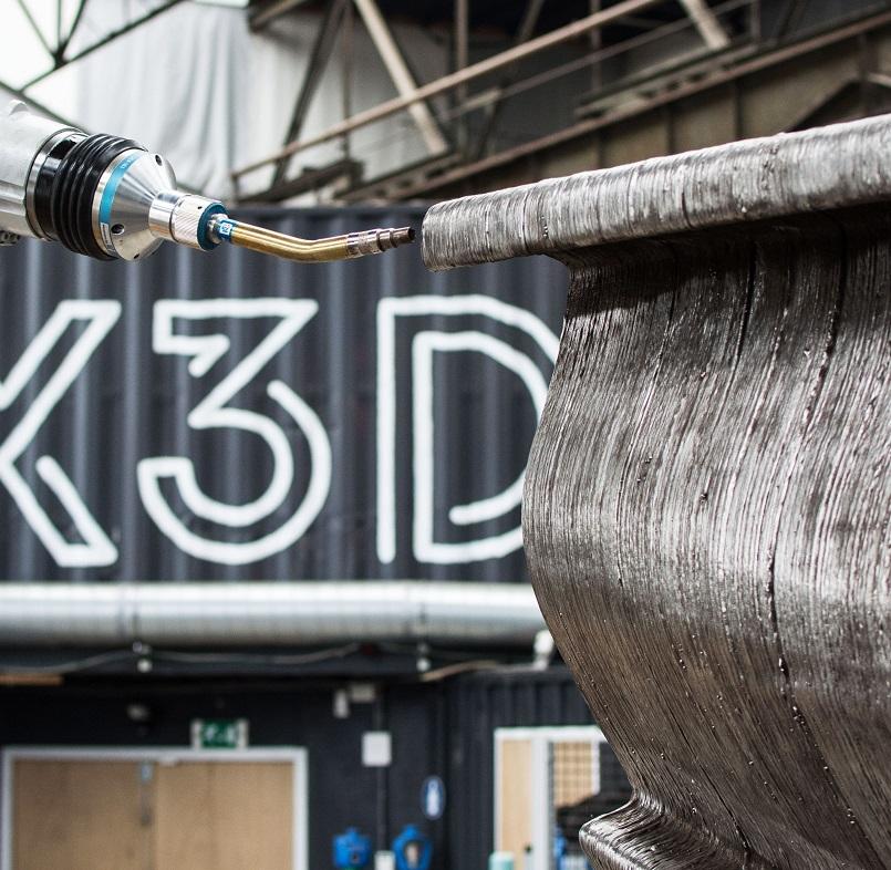
This wire-arc additive manufacturing (WAAM) setup from MX3D uses conventional welding wires and power sources, combined with unique software to control the way the robot deposits layer after layer. The technology has been set up to print very large parts, including bridge components. MX3D
With that, the bridge was finally ready. Six years after the project launched, the bridge was installed over a canal in Amsterdam and opened to the public.
And those gauges remain, there to gather performance data for years to come—monitoring changes and, perhaps most important for structural fabricators, measuring exactly how 3D-printed stainless steel behaves over time.
Such data is what the construction industry needs. With more testing and experimentation, enough data, and enough technological progress, WAAM and other additive processes have a better chance of being widely adopted in structural fabrication and elsewhere in the construction supply chain.
Structural metal fabrication seemed to be an industry that, until recently, seemed utterly impractical for additive manufacturing. In the not-too-distant future, structural fabricators might be using robots to not only join beams and plates but also build specialized components from scratch, one layer at a time.
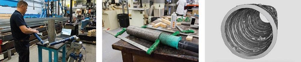
The research team used laser scanning and created a silicon mold of the inside diameter to get a complete picture of a 3D-printed tube surface. Leroy Gardner


The Fabricator is North America's leading magazine for the metal forming and fabricating industry. The magazine delivers the news, technical articles, and case histories that enable fabricators to do their jobs more efficiently. The Fabricator has served the industry since 1970.
start your free subscription
Easily access valuable industry resources now with full access to the digital edition of The Fabricator.

Easily access valuable industry resources now with full access to the digital edition of The Welder.

Easily access valuable industry resources now with full access to the digital edition of The Tube and Pipe Journal.

Easily access valuable industry resources now with full access to the digital edition of The Fabricator en Español.
In this episode of The Fabricator Podcast, Caleb Chamberlain, co-founder and CEO of OSH Cut, discusses his company’s...


