


How to improve GMAW efficiency in the fab shop
These tips can introduce a new level of productivity in the welding department
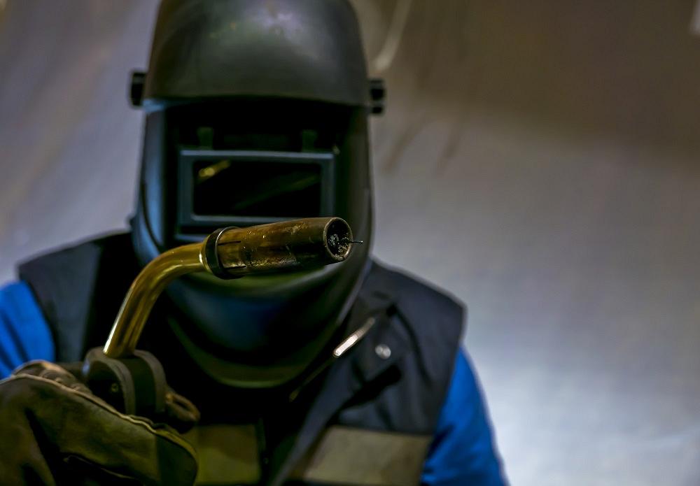
Some simple rules of thumb can improve a shop’s MIG welding performance. Getty Images
Gas metal arc welding (GMAW) is ubiquitous in metal fabricating companies around the world. The welding process is prized because a skilled welder can work rapidly and deliver high-quality joints. Additionally, the process can be used in all positions.
The welding process may be common, but that doesn’t mean every shop is full of GMAW experts. Even with experienced welders, a shop can look to improve. These rules of thumb can help any shop’s welding department reach a new level of efficiency. It’s just a matter of paying attention to the material and the welding process.
1. The cost of cleaning is less than the cost of rework caused by a weld made on a contaminated surface.
The best welds come from clean metal-to-metal contact. Any foreign material in the welding area can cause welding imperfections or porosity, the No. 1 failure of GMAW. The most common cause of porosity is welding a dirty, oily, or corroded surface. All these contaminants get trapped in the weld, resulting in holes that resemble a sponge.
Cleaning the surface prior to welding includes grinding or removing carbon, scales, oxides, paint, rust, dirt, and other surface contaminants using an organic solvent, such as acetone, or a mild alkaline solution, like a strong detergent. A stainless steel wool or wire brush should be used on the area to be welded.
2. Firmly attach the clamp to bare metal as close as possible to the arc.
Another common failure with GMAW is a bad work lead connection. The wire feeder is going to continue to pump out welding wire anyway even if the welding gun is sputtering and stuttering.
Additionally, applying and maintaining proper grounding methods within the welding area are important to promote electrical safety in the workplace.3. If you are welding vertically, horizontally, or overhead, keep the weld pool small for the best weld bead control and use the smallest wire diameter possible.
Control of the GMAW process is literally in your hands. That’s why a skilled set of hands can prove to be a very productive tool.
The most effective gas metal arc welders use both hands whenever possible. They rest the crook of the gun neck in one hand and hold the part with the trigger in the other hand.
The most common way to perform GMAW is to push the gun toward the direction of the weld, also known as the forehand method. This method produces shallow penetration with a flat, wide, and smooth surface.
The second approach comes when you drag the gun, also called the backhand method. This produces a deep-penetration weld that is narrow and high in the center.
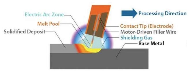
Figure 1
This diagram demonstrates the effectiveness of gas metal arc welding. The wire consistently feeds into the melt pool, and the shielding gas protects the weld pool from impurities.
Direct current electrode positive (DCEP), or reverse polarity, is the standard polarity for GMAW and for shielded metal arc welding. DCEP is produced when the electrode is connected to the positive terminal of the welding power source. In this condition, the electrons flow from the work to the electrode tip, concentrating about 70% of the heat of the arc at the electrode and 30% at the work.
Direct current electrode negative (DCEN) is produced when the electrode is connected to the negative terminal of the power source. Because the electrons flow from the electrode to the plate, approximately 70% of the arc’s heat is concentrated at the work and approximately 30% at the electrode end. DCEN is suitable for welding most metals.
4. Remember to match drive rolls, gun cable liner, and contact tip to the wire size. Also, to ensure high-quality welding, change the tip after consuming 100 to 150 lbs. of wire.
Surprisingly, this basic matching up of accessories with consumables is often ignored. If you are trying to run 0.030-inch wire through 0.035-in. rolls, you will find yourself constantly changing feed speed and never getting that setting right, as the grooves on the rolls are too large. The same applies to the gun cable liner and contact tip size. Worn contact tips are typically oval and lead to an erratic arc. Also, if a tip enters the molten weld pool, it should be immediately replaced.
5. With a constant-voltage power source, amperage is directly related to melt-off rates. When amperage decreases, the melt-off rate decreases, and when the amperage increases, the metal-off rate increases.
The typical GMAW electrodes for steel are a solid wire ranging in thickness from 0.023 in. to 0.045 in.
A single electrode size can be used to weld a range of metal thicknesses because machine setup determines the metal thickness that will be welded. Most mild steel is welded with an ER70S-6 electrode and a shielding gas mixture of argon and CO2 or just 100% CO2.
Obviously, equipment that creates the arc is at the heart of the GMAW process. These power sources are designed to transform the power from the grid into controlled values of voltage and current suitable for the intended uses. Welding processes use direct current (DC), alternating current (AC), or pulsed current.
Power sources are generally classified as constant current, constant voltage, and pulse welding.
Constant-current power sources are used primarily with coated electrodes. This type of power source has a relatively small change in amperage and arc power for a corresponding relatively large change in arc voltage or arc length—thus the name constant current. When you are welding with coated electrodes, you set the output current, or amperage, while the voltage is designed into the unit. You can vary the arc voltage somewhat by increasing or decreasing the arc length. A slight increase in arc length causes an increase in arc voltage and a slight decrease in amperage. A slight decrease in arc length causes a decrease in arc voltage and a slight increase in amperage.
Constant-voltage power sources are used in welding with solid and flux-cored electrodes, and as the name implies, the voltage output remains relatively constant. On this type of power source, the voltage is set at the machine, and amperage is determined by the speed that the wire is fed to the welding gun. Increasing the wire feed speed increases the amperage, and decreasing the wire feed speed decreases the amperage.
However, if you are using a constant-voltage power source and a wire feeder that delivers the wire at a constant speed, arc length inconsistencies caused by operator error, plate irregularities, and puddle movement are automatically compensated for by the characteristics of this process.
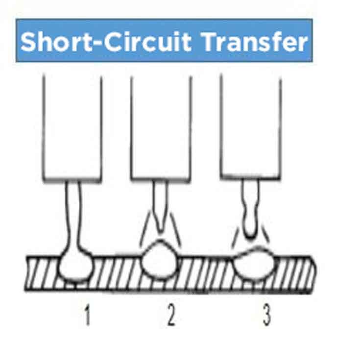
Short-circuit transfer occurs when the welding wire actually touches the base metal between 90 and 200 times per second. With short-circuit transfer, wire feed speeds, voltages, and deposition rates are usually lower than with other types of metal transfer, such as spray transfer. This makes short-circuit transfer very versatile, allowing you to weld on thin or thick metals in any position. The limitations of short-circuit metal transfer are a relatively low deposition rate, more spatter, and a lack of fusion on thicker metals. Rule of thumb: Short-circuit transfer usually has a crackling (bacon frying) sound when a good condition exists.
Pulse welding delivers waveform-controlled output, which is achieved through modern electronic controls, especially from inverter supplies. These controls can manipulate the welding current so that droplets of molten metal are dropped into the weld pool. This type of control allows for the creation of predetermined optimized programs that can be saved in the computer memory and run multiple times when called upon.
Polarity, waveform shape (either sinusoidal or square), peak and background current (pertaining to metal transfer), and frequency are the control parameters that are manipulated to create a welding program. Material, size, consumables, feed rate, travel speed, and shielding gas help to determine how those parameters come together to create the right welding program for the job.
6. Equipment intended for continuous operation should be capable of delivering the rated maximum output at 100% duty cycle.
Besides the maximum current rating, an important limiting factor to be taken into account when selecting a power source is its duty cycle, which represents in percentage the amount of time in a 10-minute average interval that the source can deliver its maximum rated power without overheating. The off time is needed to allow cooling down of the sensitive elements to a safe temperature.
7. For better penetration, keep the arc at the leading edge of the weld puddle.
The exception to this rule would be when welding thin sheet metal. In this case, keep the arc farther back in the puddle to prevent burn-through.
The basic operation of the GMAW process occurs when an electrical arc is established and maintained between a base material and a continuously fed wire electrode. The molten weld pool is shielded from the atmospheric contamination by an envelope of shielding gas that is flowed continuously around both the wire filler metal feeding in the weld pool (see Figure 1).
A welding arc requires a smooth flow of electricity through a complete electrical circuit. The current will seek the path of least resistance, so if care is not taken to place the welding ground close to the arc, the current may find another pathway.
The heat of the electrical arc serves to locally melt the base metal as well as melt the wire filler metal that is being fed into the weld.
8. Keep the distance the wire sticks out from the end of the gun’s contact tip to between 1/4 and 3/8 in. This simple tip can have the biggest effect on GMAW performance.
Always keep an eye on burn rates and feed rates. The burn rate refers to the amount of wire filler metal (measured in inches per minute) that is melted or consumed by the arc’s thermal energy. The primary variables that control the thermal energy of the arc are the welding current, welding voltage, and shielding gas composition. The feed rate simply refers to the rate (also measured in inches per minute) that the wire filler metal is fed into the weld.
For a stable welding arc, the burn rate and feed rate need to be equal. For instance, if the burn rate is higher than the feed rate, the wire filler metal melts back to the contact tip and causes failure. With the exception of short-circuit metal transfer, if the feed rate is higher than the burn rate, the wire filler metal feeds into the molten weld pool, causing failure.
If you are concerned about the penetration profile into the base metal and weld bead profile above the base metal, look into these main variables:
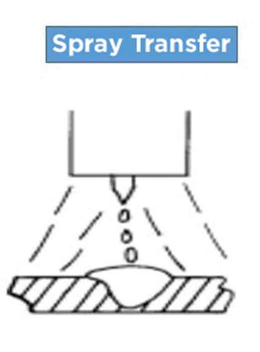
In the spray transfer mode, tiny molten droplets are sprayed across the arc from the electrode wire to the base metal. Spray arc transfer uses relatively high voltage, wire feed speed, and amperage values when compared to short-circuit transfer. To achieve a true spray transfer, an argon-rich shielding gas must be used. The advantages of spray arc transfer are a high deposition rate; very little spatter; good fusion and penetration; good bead appearance; and the ability to use larger wire diameters. The main limitation of the mode is that it can be used only when working with 1/8-in. or thicker material. Rule of thumb: When proper parameters are used, the spray arc transfer mode produces a characteristic humming or buzzing sound.
- Welding current
- Welding voltage
- Contact-tip-to-work distance
- Arc travel speed
In the GMAW process, welding current is directly related to wire feed speed (if the wire extension is constant). As the wire feed speed is varied, the welding current varies in the same direction. In other words, an increase (or decrease) in the wire feed speed causes an increase (or decrease) of the current. This relationship is commonly called the burnoff characteristic.
The welding voltage is the voltage between the end of the wire and the workpiece. Because of voltage drops encountered in the welding system, the arc voltage cannot be directly read on the power source voltmeter. Welding voltage (arc length) has an important effect on the type of process variation or metal transfer desired. Short-arc welding requires relatively low voltages, and spray arc requires higher voltages. It should be noted, too, as welding current and wire burnoff are increased, the welding voltage must also be increased somewhat to maintain stability.
Contact-tip-to-work distance is the combination of arc length and electrode extension (see Figure 2). Electrode extension is the distance between the last point of electrical contact, usually the end of the contact tip, and the end of the wire electrode.
The contact-tip-to-work distance, because of its effect on the wire extension, affects the welding current required to melt the wire at a given feed speed. It is important to understand that the welding current requirement can vary with the contact-tip-to-work distance. Basically, as the tip-to-work distance is increased, the amount of heating increases and the welding current required to melt the wire decreases. The converse also is true.
Long extensions result in excess weld metal being deposited with low arc heat. This can cause poor bead shape and low penetration. In addition, as the contact-tip-to-work distance increases, the arc becomes less stable. For short-arc welding, a 3/8-in. contact-tip-to-work distance is recommended. It is very important that the wire extension be kept as constant as possible during the welding operation.
The arc travel speed is the linear rate that the arc moves along the workpiece. This parameter is usually expressed as inches per minute.
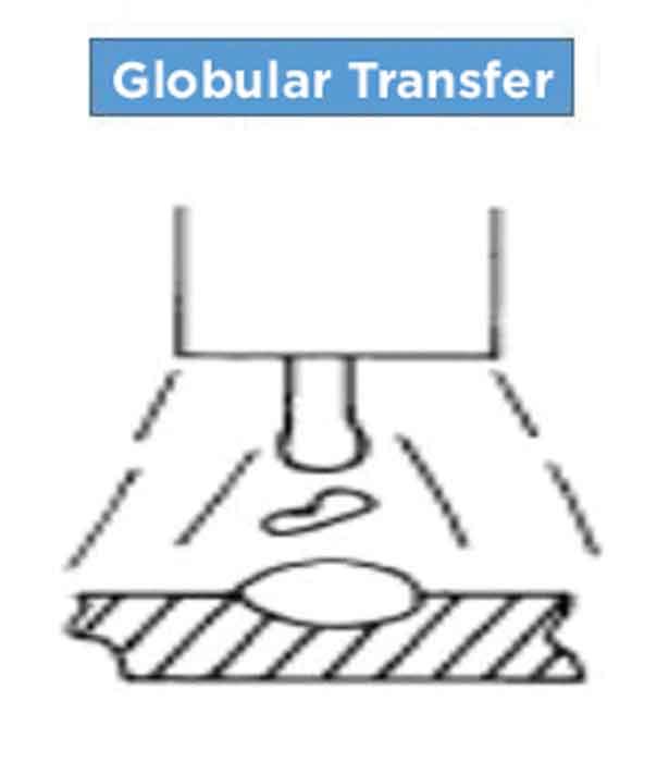
Globular transfer refers to the state of transfer between short-circuiting and spray arc transfer. Large balls of wire are expelled off the end of the electrode wire and enter the weld puddle. Shortcomings associated with globular transfer include the increased presence of spatter; a less desirable weld appearance than spray arc transfer; it is limited to welding in flat positions and horizontal fillet welds; and is limited to working with 1/8-in. or thicker metal. Rule of thumb: Globular transfer can result when welding parameters such as voltage, amperage, and wire feed speed are somewhat higher than the settings for short-circuit transfer.
Rules regarding the arc travel speed are:
- As the material thickness increases, the travel speed must be reduced.
- For a given material thickness and joint design, as the welding current is increased, so too must the arc travel speed increase. The converse also is true.
- Higher welding speeds are attainable by using the forehand welding technique.
9. On mild steel a CO2 shielding gas produces greater penetration but with spatter. An argon mixture produces less spatter but with shallow penetration.
A mixture of the two usually makes the most sense.
Shielding gas has a substantial effect on the stability of the arc, metal transfer, the behavior of the weld pool, and corresponding penetration.
Shielding gases are categorized as inert gases and active gases. Inert gases do not react with air and protect the arc and weld pool from atmospheric contamination and ensure smooth transfer of molten droplets from the wire electrode to the weld pool. Using inert gas as a shielding gas in the GMAW process is known as metal inert gas (MIG) welding.
CO2 is an active gas and very affordable, but it is far from the best for welding. CO2 produces a cooler, stiffer arc with spatter and a slightly harder weld deposit. CO2 is a particularly challenging gas to use on thin material, and not all MIG welders perform well on thicker material with 100% CO2 as a shielding gas. Using an active gas as a shielding gas in the GMAW process is known as metal active gas (MAG) welding.
An argon/CO2 mix produces far superior results as the arc is softer and smoother, and the resulting weld deposit is slightly softer and more malleable.
Use this guide when choosing the correct shielding gas mixture:
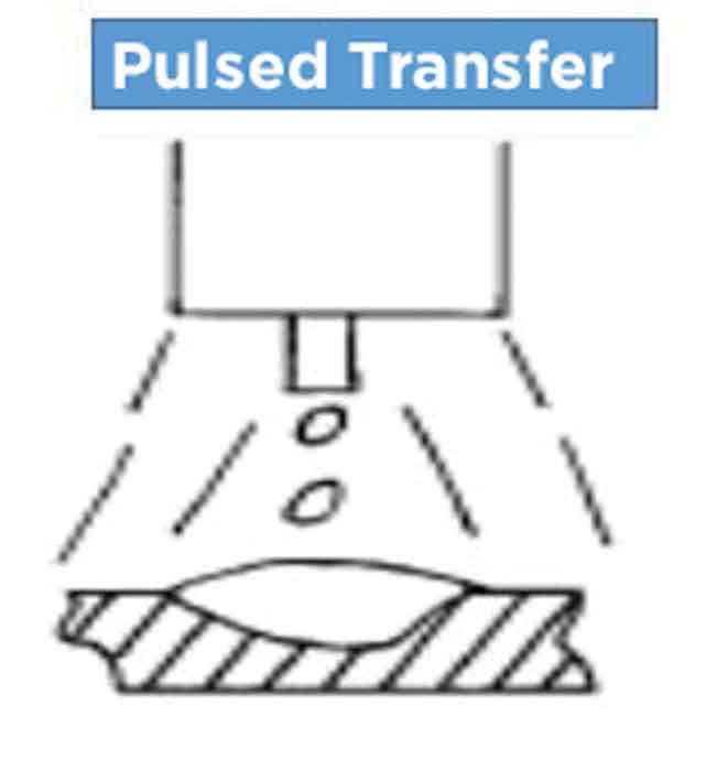
Pulsed transfer is a mode midway between spray transfer and the short-circuit transfer mechanism. The mode can be considered “too cold” because of the noncontinuous arcing. The arc effectively goes out between each melting cycle. It produces smooth, spatter-free welding at mean currents (50 to 150 amps), which would otherwise be too low for all except short-circuiting transfer with its irregular transfer. Rule of thumb: Pulsed transfer is ideal for spatter-free welding using 50 to 150 amps on thicker sections where more heat is needed but where spray transfer is still too hot.
- 95% argon/5% CO2 is ideal for up to 1/4-in. steel.
- 90% argon/10% CO2 is ideal for 1/4- to 1-in. steel.
- 80% argon/20% CO2 is ideal for 1-in. or thicker steel.
Inert gases (argon or helium), compared to CO2, are generally more tolerant to parameter settings and generate less spatter with the short-circuit metal transfer mode.
10. Read the bead. Convex and concave shapes tell a story.
An experienced welder can interpret the welding by just looking at the weld bead. A convex weld bead shape often indicates that voltage and current are not compatible with the thickness of the base metal. Also, there might not be enough heat being produced to penetrate the base metal. Similarly, a concave-shaped bead often indicates excessive heat being produced because of inappropriate welding parameters being selected.
11.Listen to the buzz. It tells a story as well.
The sound of welding should be a steady buzz. A loud, raspy sound can indicate that the voltage is too low. A crackling sound, like a machine gun going off, can indicate a too high amperage setting. On the other hand, a steady hiss can indicate the voltage setting is too high.
Rajiv Vasdev, PE and CMfgE, has more than 20 years of engineering and manufacturing experience and currently works in the automotive parts industry. He can be reached at vasdevrajiv@yahoo.com.
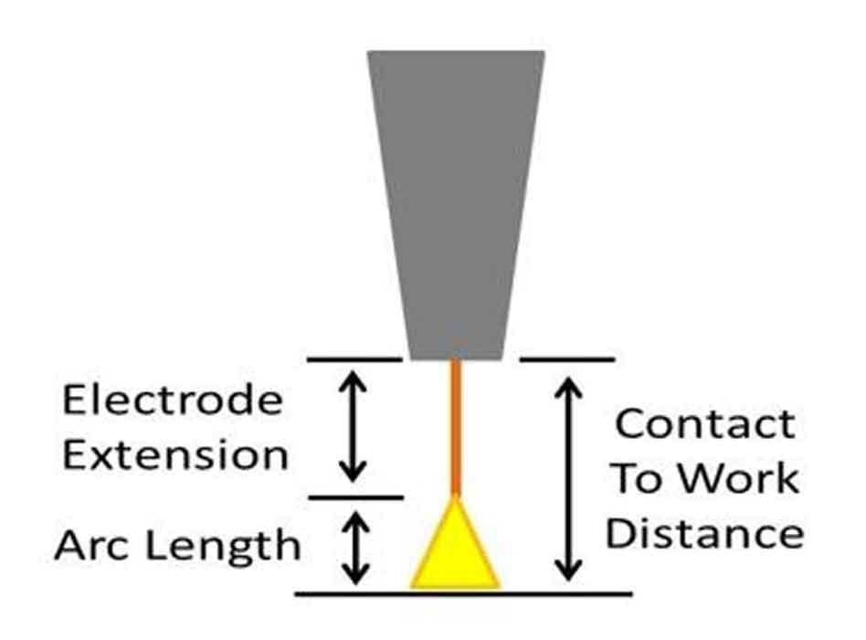
Figure 2
Keeping the electrode extension between 1/4 in. and 3/8 in. can help you maintain a consistent bead.
About the Author

Rajiv Vasdev
About the Publication

subscribe now

The Fabricator is North America's leading magazine for the metal forming and fabricating industry. The magazine delivers the news, technical articles, and case histories that enable fabricators to do their jobs more efficiently. The Fabricator has served the industry since 1970.
start your free subscription- Stay connected from anywhere

Easily access valuable industry resources now with full access to the digital edition of The Fabricator.

Easily access valuable industry resources now with full access to the digital edition of The Welder.

Easily access valuable industry resources now with full access to the digital edition of The Tube and Pipe Journal.

Easily access valuable industry resources now with full access to the digital edition of The Fabricator en Español.
- Podcasting

In this episode of The Fabricator Podcast, Caleb Chamberlain, co-founder and CEO of OSH Cut, discusses his company’s...
- Trending Articles
1
Capturing, recording equipment inspection data for FMEA

2
Tips for creating sheet metal tubes with perforations

3
Are two heads better than one in fiber laser cutting?

4
Supporting the metal fabricating industry through FMA

5
Omco Solar opens second Alabama manufacturing facility
