


Marketing Specialist
Thossaphol/iStock/Getty Images Plus
Ever since the development of automated welding, operators have had to monitor the process to ensure that all parameters are properly adjusted; that the welding head is properly aligned with the weld seam and workpieces; and that the weld pool, weld bead, and other features are all formed correctly.
The most basic method of monitoring is for the operator to view the process directly wearing a welding helmet and protective screen, which contain a dark green filter to remove most of the harmful content of the radiation coming from a welding arc.
Since the advent of video camera technology in the 1950s, numerous attempts have been made to use video cameras to acquire images of an open arc weld, relieving operators from working in hazardous proximity to the welding process and providing a better view of the welding arc. However, most standard video cameras—even with the better technology available today—are able to capture a range of brightness of only about 1,000:1 in an image, whereas the range of brightness in the vicinity of an open arc weld exceeds 10,000,000:1. This usually results in an image of the weld that is completely saturated, providing no valuable information about the brightest area of the image.
For a camera to monitor a welding process properly, it must be able to capture content at the low end of brightness (the background around the weld), as well as at the high end of brightness (the weld arc in the foreground)—known generically as high-dynamic-range (HDR) imaging.
Methods and technologies currently available to achieve HDR imaging of a live welding arc include:
Most of these approaches do not allow for reliable evaluations of the welding process because some portions of the weld environment will be overexposed or underexposed, causing the image to lose critical detail that the welding operator needs.
The simplest way to see the detail of an open arc is to reduce the amount of light available to a standard camera by using a dark filter across all or part of the lens. If a dark filter is used across the entire lens, the two main challenges are:
Early cameras were equipped with dark filters that were not removable. They provided good definition of the weld arc, but not much was visible. The first successful method to achieve a better view of the background was to implement a dark spot filter in front of the camera, aligning the spot with the open arc and thereby obscuring the brightest part of the arc weld.
The problem with this approach is that the image has to be lined up properly with a spot filter with the right size and darkness to darken the weld sufficiently. If the alignment, filter size, or darkness isn’t correct, the resulting image isn’t ideal. Even with the best setup, light from the weld arc often bends around the dark spot and creates hot spots on the rest of the image. And when the arc is turned off, the dark spot remains in the field of view, impairing the operator’s ability to see all the details of the weld work environment with the welding gun off.
To allow the welder to see all the details in a weld environment clearly when the weld arc is not present, some designers have incorporated a switchable iris into the spot filter. This provides for some significant improvement to the image quality because the spot filter can be removed, when not required, by pulsing the iris.
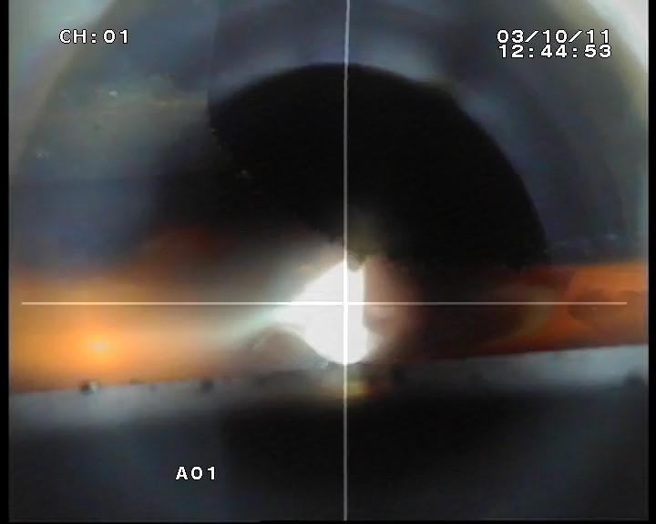
This weld image was captured by a camera equipped with a spot filter. Xiris Automation Inc.
The original switchable-iris systems were electromechanical. While achieving a better image than a stationary spot filter when no welding was present, the electromechanical system’s reaction time to change the brightness was too slow to be a useful light-shuttering technique, especially on processes that have huge brightness swings, such as short-circuit GMAW.
A slight improvement on a switchable-iris system was a switchable polarizing filter. In this approach, a single filter was put in place and the second filter, the polarizer, was rotated until the polarizing element created a dark filter. With better designs, the polarized element was a single spot in the middle of the optical path. However, polarizing filters still are not dark enough for some type of welding processes and need to be activated quickly to respond to the arc-on condition.
Another option is a liquid crystal display (LCD) filter, which can switch very rapidly from clear to dark. However, the clear state remains fairly dark, and the dark state is not dark enough for some applications. To drive the display, the filters need a photodiode to detect if the weld is on.
Another approach to creating an HDR image is photochromic optics. A photochromic lens contains a chemical layer that automatically darkens on exposure to ultraviolet (UV) radiation emitted from a weld source. Once the light source is removed by shutting off the weld source, the lens gradually returns to its clear state. The process is similar to eyeglasses that darken in bright sunlight and return to clear in darker environments.
The drawback to this technology for HDR imaging is that photochromic lenses are slow to darken and even slower to lighten, delaying the time it takes for a camera to be useful to the operator. The photochromic process also tends to decay over time, so that eventually it cannot darken enough to be useful.
A nonoptical technique now used to achieve HDR imaging is to combine multiple images of the same scene taken extremely quickly with different exposures. A composite video frame is created by mathematically combining the multiple consecutive frames using a tone-mapping operator.
This method, known as the Wyckoff method, works well with relatively slow-changing scenes, as long as the parameters used in the mathematical combination are well-defined and unchanging. But in welding, the scene brightness can change so fast that two consecutive frames may differ in brightness in many parts of the images. Consequently, it’s very difficult to create a single mathematical combination of consecutive images that generates a final image with smooth light gradations across all the different types of welding, their pulsing modes, and other varying parameters.
This method also has another challenge: a reduced frame rate. To keep a smooth frames-per-second video rate, the camera must produce many times that frame rate to provide enough frames to be mathematically combined. The result is that this process tends to have extensive computer or electronics hardware that can be cost-prohibitive.
Instead of varying the exposure time of successive images, an HDR image could be approximated by using a camera equipped with an extended shutter. In such a camera, the user can set up multiple slope integration curve segments to extend the dynamic range of the camera by generating a nonlinear response to light.
The multiple slope operation is controlled using knee points (points that define a change of slope between two linear segments of the response curve), where each knee point occurs at a separate time during the overall integration time of the sensor. Each knee point represents a separate reset point for the image, where pixels brighter than a certain value are reset to that value. The value that is set for each knee point is the time from the start of integration to when the knee point occurs. Each knee point must have a greater time than the previous knee point, and all knee point times must be less than the overall integration time. The effect in the image is to reset the pixel at that time and to integrate until the end of the overall integration time. Hence, as the knee point time becomes longer, the effect is to shorten the integration time and expand the dynamic range in bright areas of the image.
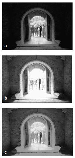
The Wyckoff method achieves HDR imaging by combining multiple images of the same scene taken extremely quickly with different exposures. Here the original raw images—underexposed (a) and overexposed (b)—are combined using tone mapping into an image (c) that shows greater detail. hi.eecg.toronto.edu/Wyckoff.html
If a camera is equipped with an extended shutter and knee points, an HDR image can be achieved because different rates of brightness compression can be achieved along the brightness curve—reducing the saturation at the high end and stretching the range of brightness at the low end. The user can adjust the knee points to compress or expand certain ranges or to reduce the charging rate of the camera’s pixels after they become saturated.
The resulting response curve provides some HDR, similar to a logarithmic response. However, a knee point camera’s design allows the possibility for pixel blooming and saturation effects around very bright pixels. In addition, setting knee points can create a suitable HDR image with one set of image brightness parameters, but when the parameters change as they would from one type of welding to the next, the knee points have to be reset by the operator, making such a camera difficult to use across a variety of welding processes.
A few years ago, a new technology was introduced for complementary metal oxide semiconductor (CMOS) sensors based on photovoltaic pixel sensors. Such sensors have a natural logarithmic response that does not saturate, and there is no blooming effect because there are no accumulated charges. The pixels on these sensors deliver a voltage proportional to the logarithm of illumination, generating a dynamic range greater than 140 dB and achieving HDR imaging.
This technology can perform incident light intensity measurement with no integration of the signal on the sensor. And the advanced background noise removal method allows these sensors to view the scene at normal light conditions and dark conditions while simultaneously viewing bright objects without needing any changes.
Cameras built from such a sensor offer a number of improvements over traditional cameras:
New techniques continue to appear on the market to try to achieve higher and higher levels of high dynamic range imaging. Numerous sensors have been developed with HDR ranges that approach 100 dB using patented processes such as interlaced lines of an image with two levels of sensitivity with a rolling shutter, dual-sensor cameras with different ranges of intensity, and variable integration time sensors that extend the range of brightness. All of these technologies have promise but end up yielding a lower range of brightness than that available from a logarithmic CMOS sensor.
Another consideration in the use of HDR video cameras with welding processes is the type of exposure sequence used in the camera sensor. Originally, all HDR digital camera sensors used a rolling scheme, in which the sensor is exposed to light one line at a time, so one line would be exposed and its current charges readout, then the next line, and so on. When imaging any rapidly changing scene, such as a pulsed welding arc, the resulting image can contain artifacts that result from the arc flash being significantly shorter than the time to expose the full frame.
Fairly recently, global shutters have been implemented in HDR digital camera sensors. A global shutter is an image-acquisition process whereby the entire image is exposed at one time. When imaging welding processes, this technique provides consistent image features across the entire image, minimizing localized artifacts caused by the varying weld arc while the frame is being exposed; all portions of the image are affected equally.
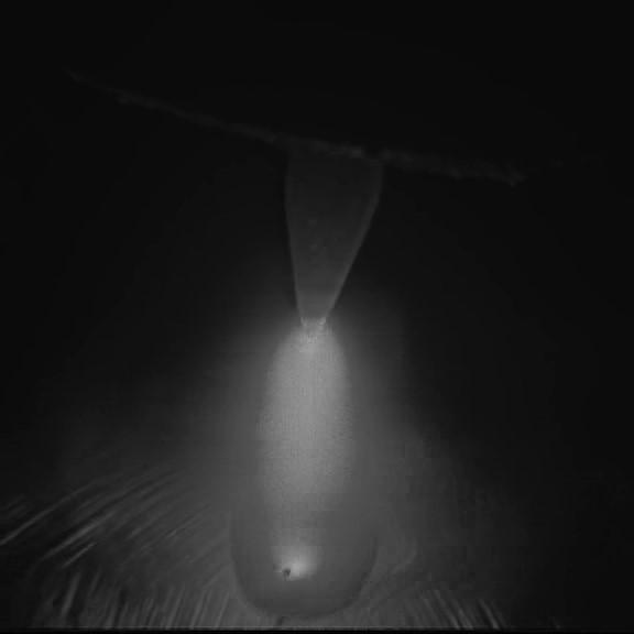
In this image of a GTAW captured by a logarithmic CMOS sensor, many details of the welding process, including the arc and background, are visible to the operator for diagnostics, process adjustment, and validation. Xiris Automation Inc.


The Fabricator is North America's leading magazine for the metal forming and fabricating industry. The magazine delivers the news, technical articles, and case histories that enable fabricators to do their jobs more efficiently. The Fabricator has served the industry since 1970.
start your free subscription
Easily access valuable industry resources now with full access to the digital edition of The Fabricator.

Easily access valuable industry resources now with full access to the digital edition of The Welder.

Easily access valuable industry resources now with full access to the digital edition of The Tube and Pipe Journal.

Easily access valuable industry resources now with full access to the digital edition of The Fabricator en Español.
In this episode of The Fabricator Podcast, Caleb Chamberlain, co-founder and CEO of OSH Cut, discusses his company’s...


