


Senior Editor

An alternative, automated approach to connection design with cloud-based analytics software could have profound implications for metal fabrication, erection, and the overall construction timeline. Getty Images
As a longtime detailer, Henry Lederman knew the drill. Most structural fabricators had standards that defined the way they did things. Some were ¾-in. bolt shops that liked to use double-angle connections. Others preferred shear plates. And everyone abided by industry-standard 3-in. vertical spacing for the bolts.
The fab shops would turn those standards over to the detailing firm and connection engineers, who would design connections based on those standards and historical practices. When everyone signed off, the drawing would be released and it was off to the races, with everyone aiming to eke out the most profit while fulfilling the owner’s need to complete the building as quickly as possible.
“It’s as if everyone is jumping into a fast-moving river,” Lederman said. “They go up for air now and then, but for the most part, they don’t have time to breathe. They don’t have time to plan and to get the data in a form that can really help make decisions that are best for the company and the project.”
A lot of that data lies hidden forever, especially within a part of structural fabrication that literally ties everything together: the connections. But what if connection engineers could iterate their designs in an efficient way, to explore all the connection possibilities? What effect would that have on the value stream of the entire project as it flows from engineering and detailing to fabrication and erection?
From this sprung the idea behind Qnect. Founded in 2013, the company has developed a cloud-based analytics software that effectively automates connection design. According to the company, having the ability to iterate millions of connection possibilities has significant implications for the entire structural steel arena.
Industrial and precision metal fabricators serving OEMs and general industry know the benefits of designing for manufacturability. Most fab shops would agree that the more input they get on a product’s design, the more efficient the actual fabrication is likely to be. It’s better to fix something in the design stage rather than being forced to “make it work” on the fab shop floor.
Structural fabricators face similar challenges, which is why they’ve developed standards. A fabricator that defines itself as a “¾-in. bolted shop” has built all its fabrication processes around those kinds of connections. The connection engineers have their own standards, too, because, like the structural fabricator, standards streamline things. Sure, engineers could iterate connection designs, but doing so takes time, with umpteen calculations to ensure loading requirements are met, all while ensuring the new designs abide by industry standards, like those from the American Institute of Steel Construction (AISC).
“All this just didn’t seem like a good system where you have all these discrete parts [of the project value chain] acting as their own profit centers,” said Lederman, Qnect’s co-founder and chief strategy officer. “The detailer is a profit center, and so is the connection engineer, the fabricator, and the erector. And they don’t always work in each other’s best interest.”
If a project is a fast-flowing river, the best way to change how it flows is at the headwaters where, in the world of structural steel construction, the detailers and connection engineers work. Of course, to truly change the headwaters, you’d need to allow connection engineers to comb through millions of connection iterations to find not just the right connection for a single vertical brace, but the right combination of connections for an entire building—a combination that would benefit not only the building’s design requirements but also the structural fabricator and erector. This would have been a quixotic endeavor a few decades ago, back when the industry lacked something that would make such an endeavor practical: computing power.
“For a vertical brace, we iterate over a billion possibilities to determine what the best connection is,” Lederman said. “You need serious computing power to run so many calculations. It doesn’t help to do those billion calculations if you have to wait a week. This is where cloud computing comes into play. We’re working with Amazon Web Services, which allows us to use as many or as few computers we need for a particular job.
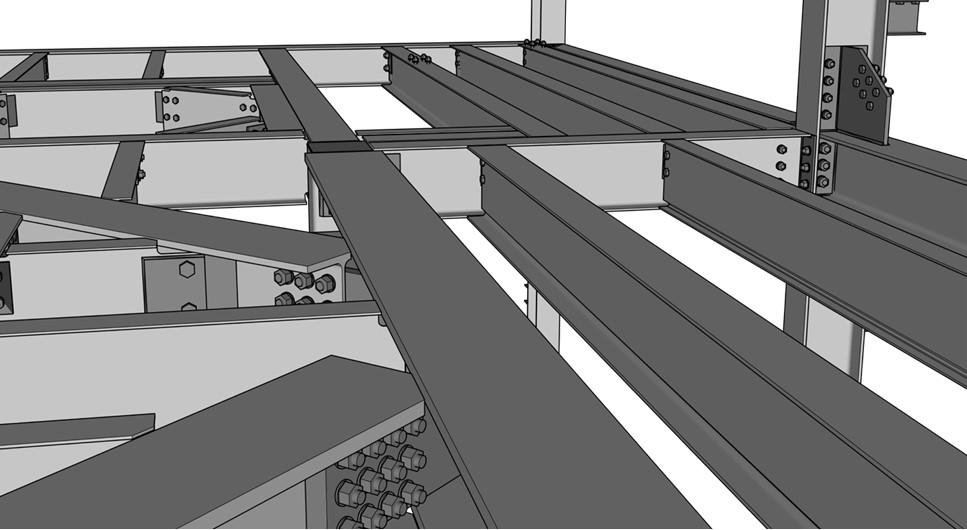
This design uses bolt optimizations to reduce bolt quantities, which can reduce costs and erection time.
“Now, if detailers and fabricators say they need about six weeks to do the connection engineering and modeling, the software can do it in about an hour. If it takes them six months to engineer and detail, the software has been able to do such a project in about three hours.”
Connection engineers still need to review the results, of course. The entire process still requires human intervention, and it always will. “All the engineering has to be PE stamped by a connection engineer,” Lederman explained. “Also, every Qnect joint is consistent, defined by all the limit states of the AISC codes.”
Shortly after launching in 2013, the company tested its software through peer review. As Lederman recalled, “We received many positive comments. But we had a few cases in which connection engineers challenged us, only to find out we had a more refined approach to the connection.”
Using software that iterates design connections automatically, simultaneously ensuring connections adhere to load requirements—all while following a baseline of AISC standards—the connection engineer now can offer options upfront, at the headwaters of the project.
Lederman first gave a simple example: changing the 3-in. vertical bolt spacing. “It’s a basic requirement and recommended practice that the connection basically needs to be half the depth of the beam. But in order for it to be half the depth, and if you’re using 3-in. spacing, you might have to add a couple more bolts. If you simply designed the bolted connection with a 4-in. spacing, you’d solve the problem.” Fewer bolts lead to less drilling, a lot less erection time, and fewer bolt-related injuries.
The right connection strategy also can help reduce fabrication costs by allowing for single-station fabrication: that is, the fab shop needn’t tie up a bridge crane to move a beam to another station, like from the beam line to welding. The software color-codes members to help the connection engineer identify the number of required workstations. One color might signify members that need only go to the punch and drill line (a single-station fabrication), while another color shows components that go through the beam line plus welding (a two-station fabrication).
“Say you have a welded shear plate [requiring the welding station],” Lederman said. “You might try a single-angle bolted-bolted connection.” That simple connection change eliminates costly material movement on the floor.
Still, just swapping out a connection may or may not make sense, mainly because of the give-and-take nature of the construction value chain. A small savings in fabrication can lead to serious cost overruns in erection due to more on-site bolting, welding, insufficient erector aids—the list goes on.
This is why early data analytics and the computing power behind it are so important. “No matter the building’s size, the software iterates connections for the entire structure,” Lederman said. “It will try different bolt diameters. It will try single-angle connections, shear plate connections, extended shear plate connections, double-angle welded connections, bolted double angles, and more. It will then output a report, with the cost and bolt quantities, so fabricators can do an analysis of what joint configuration makes the most sense for the entire project.”
The ability to weigh all the trade-offs has far-reaching implications. Consider a job that requires hundreds of copes, a costly operation for a structural fabricator that copes manually. “But the only way to get rid of coped beams is to use a welded extended shear plate,” Lederman said, “where the plate is pulled out of the girder. But when you do that, it can get more expensive. You might need more columns of bolts [in a connection], or the plates might get so thick that you need double-pass welds.” With so many unknowns, connection engineers take the conventional route, keep the coping requirement, and use conventional shear plate connections.
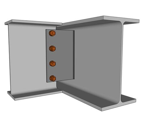
An extended shear plate eliminates beam copes and optimizes bolt spacing.
Data analytics, however, changes this situation. “You can do this data analysis in estimating. With software, you can run the entire building with extended shear plates, and it will show the exact plate thickness, the number of bolts, the weld sizes,” Lederman explained. “With this early data, everyone can make a decision regarding the trade-off between eliminating hundreds of copes versus using extended shear plates.”
If the software shows that extended shear plates are indeed possible and efficient, the erector’s job becomes much easier. “If you have extended shear plate connections, that’s the fastest erection for any erector, which means they can do more picks in less time. And if you have fewer bolts for the erector to install, that saves time and decreases costs.”
Lederman described a current project involving hollow structural sections. Before the job got to the fabricator, he worked with the engineer to produce a model with all the gussets in it. Having all this data upfront helps the ideals behind building information modeling (BIM) come to fruition. “The model allowed us to do a lot of BIM coordination for MEP [mechanical, electrical, and plumbing], so everyone can start to improve the situation and save a lot of effort downstream.”
When designing connections, Qnect usually retrieves load information in one of three ways: the uniform design load (UDL) factors on the engineering drawings; a load table provided by the engineer; or loads indicated on the design drawings, which can be put into the 3D model.
“Currently we are able to take loads right from the engineering software,” Lederman said. “Today we’re converting design drawings into the Tekla models with the loads, installing the connections with 100% detailing. Engineers can then observe any issues and improve their designs. And we can do that many times before plunging into the fast-moving river [of the construction value chain].”
On Steel Day in September 2019, AISC announced its initiative to cut in half the time it takes to design and construct a building by 2025. “When AISC announced this, some people asked, ‘Is this crazy?’” Lederman said. “But that’s the wrong question to ask. The real question is, how would you do it? It starts with technology.”
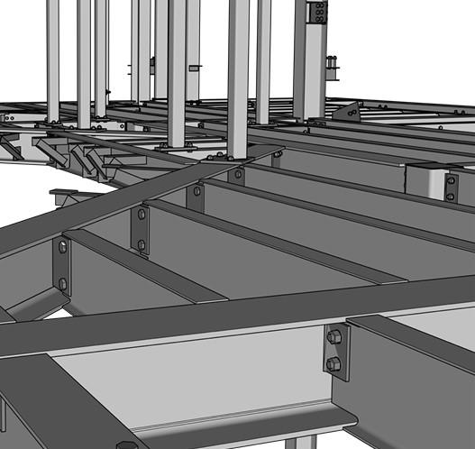
These skewed connections, designed to take heavy loads, require no coping.


The Fabricator is North America's leading magazine for the metal forming and fabricating industry. The magazine delivers the news, technical articles, and case histories that enable fabricators to do their jobs more efficiently. The Fabricator has served the industry since 1970.
start your free subscription
Easily access valuable industry resources now with full access to the digital edition of The Fabricator.

Easily access valuable industry resources now with full access to the digital edition of The Welder.

Easily access valuable industry resources now with full access to the digital edition of The Tube and Pipe Journal.

Easily access valuable industry resources now with full access to the digital edition of The Fabricator en Español.
In this episode of The Fabricator Podcast, Caleb Chamberlain, co-founder and CEO of OSH Cut, discusses his company’s...


