


Air-bending sharp on the press brake: A fight not worth fighting
Fabricators can avoid it by choosing the right tools for the job
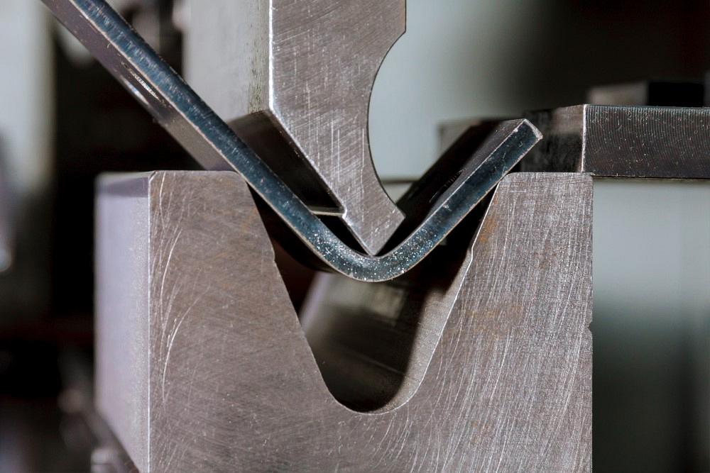
Bending sharp leads to more angular variation and frustration at the press brake. Metal fabricators can avoid the headache by choosing the right punch and die for the job. Getty Images
Question: We recently replaced our 15-year-old punches and dies with new tooling. Our old tooling still dictates our 3D modeling, and I have been tasked with changing the 3D modeling parameters, along with adjusting our press brakes to produce more accurate parts. Most are bent to 90 degrees, and each part has between two and five bends. Several are box-style, with four flanges being bent inward, but we do have some stacking parts that need to be precise to fit within one another.
We work with 60,000-PSI cold-rolled steel, galvanized material, and numerous stainless steel grades. Typical material thicknesses are between 10 and 16 ga. A few months ago, we purchased new tools to air-bend these materials. We have bottom dies that are 0.3937, 0.62992, and 0.98425 in. We use an 86-degree top punch with a tip radius of 0.024 in. Based on our tooling and material, we are forming over die openings that are about 6x the material thickness, and our top punch is producing sharp bends to the point of putting a crease into every part we manufacture, based on the 63% rule of air bending (that is, bends turn sharp when the inside radius is less than 63% of the material thickness).
Under the old tooling standard, we set our K-factor to a varying amount based on material type. Based on your suggestions from previous columns, we should be keeping our inside radius as close to the material thickness in order to get accurate angles and dimensions.
We could get punches with nose radii of 0.060 in., 0.090 in., and 0.118 in. Considering we make sharp bends more often than not, I believe the tooling options available to us should work sufficiently for our bending needs. With the right tooling lined up, the blanket 0.031-in. inside radius we set in our 3D modeling would be adjusted for the material type once we get the new punches.
Using calculations from your website, the K-factor would then be calculated correctly, and therefore the parts would have the correct bend deduction. Would this be the best course of action to get our parts to be more accurate?
Answer: Let’s start with the dies and die openings. The chart in Figure 1 shows the angle variation that can be expected based on the material thickness and die opening. The smaller the die opening gets relative to the same material thickness, the greater the amount of angle variation you will need to deal with during forming.
Choosing a Die Opening
The 6x rule you are working with, while safe to do in most cases, is exacerbating your forming issues. A die opening 8x the material thickness may give you angular variation averaging ±1 degree to ±1.5 degrees. Using a die that’s only 6x the material thickness will increase that angle variation to 3 degrees. You might have a real need to use a die opening that small relative to the material thickness—catching a short flange, for example. Otherwise, 8x is a much better choice and will help stabilize your flange-to-flange variations.
The more stable your bend angles, the more consistent your linear dimensions will be, and the more exceptional your finished products.
All this assumes that you are forming a radius that’s a perfect bend (where the inside radius equals the material thickness), a minimum radius, or a sharp radius. Suppose you form a radius that exceeds 125% of the material thickness. In that case, the die selection process is a little different. (For more on this, see “Radius types formed by air bending on a press brake.”)
The Punch Nose Radius
So, how does the punch nose radius play into all of this? Let’s begin with the sharp bend relationship to the material’s thickness and type. What is that relationship, and what does it mean?
Yes, a rule of thumb states that when the inside radius is less than 63% of the material thickness, the bend turns sharp. That value works well for low-alloy mild steel. But again, it is only a rule of thumb, and there are more accurate ways to predict where a bend turns sharp. This is something I will cover in detail in a future column. Once you know where the bend turns sharp, you can then avoid going there—unless you need to, of course. (A free sharp bend calculator is available under the “tools” tab on my website.)
In most cases, a sharp-bend relationship will create a crease on the inside center of the bend. When the nose radius is too small relative to the material thickness, the tonnage to form becomes concentrated into too small of a surface area. At that point, the material can no longer resist the pressure, and the punch tip begins to penetrate the surface of the material. The sharper the bend, the more profound the crease.
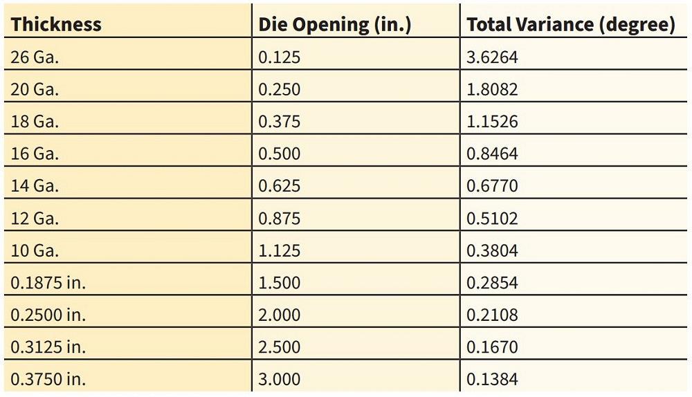
FIGURE 1. As your die opening narrows, part angle variance can grow. These variance measurements are accurate for 60,000-PSI low-alloy cold-rolled steel. Adjustments will be needed for other material types. Note that bend length also plays a role.
That crease manifests in two ways. First, unless you are bottoming or coining the part, you will see more angle variations even under the best of conditions. That’s because the crease amplifies the variables that cause the angular change in the first place. One degree of variation becomes 3 or 4 degrees of variation. All angular variations are hard enough as it is, but now, you’re try to hold consistent dimensions gauging off that 3 or 4 degrees of angular change.
The second way the crease manifests is in the bend radius. When air bending, the inside bend radius is produced as a percentage of the die opening. When a punch nose is sharp and penetrates the material, it goes right through the natural radius (see Figure 2).This causes the inside bend radius to become tighter and elongate into more of a parabolic shape rather than an actual proper radius. That messes up your bend allowance, bend deduction values, and the dimensions of the unbent flat part.
For the most stable bends, always try to use a punch nose radius that’s close as possible, but does not exceed, the natural floated bend radius. If you exceed it, you will cause the part to take on the larger bend radius of the punch nose. This again would change your bend allowance and bend deduction calculations.
Also note that the smaller the die opening is, the greater the amount of tonnage (force) is required to make the bend. And what happens to a sharp bend when the tonnage is increased? That’s right—the punch nose will penetrate further into the material being formed. This further elongates the bend radius, tightens the inside bend radius, changes the bend deduction and bend allowance calculations, and throws off your unbent flat dimensions. What else is going to happen? The further that you penetrate the nose of the punch into the material, the more pronounced part-to-part variations become, further destabilizing the finished part.
Putting the Two Together
Putting together the variations caused by the smaller die opening with the variations caused by the sharp bend, it is easy to see why consistency is hard to achieve in your products. If you want to produce better and more consistent parts, calculate the optimum die opening for the situation as much as possible and stay away from the smaller die openings unless necessary. Using larger die openings will decrease your tonnage requirements, which will also reduce the wear and tear of your press brake and tooling.
Match your punch nose radius as close as possible to the part’s floated inside bend radius. And again, do not bend sharp unless you have to. After doing all this, you will find that problems at your press brake will be less frequent and your products will improve.
Bending sharp works well if you are bottom bending, and it’s the whole point of coining. But in air forming, bending sharp is a fight worth avoiding.
Precision Press Brake Certificate Course
Master the principles of precision sheet metal bending with an understanding of the techniques, calculations, and equipment during a two-day course Sept. 13-14.
This intensive seminar will teach you the theory and math fundamentals behind the machine to uncover the secrets to working with press brakes. You’ll understand the principles behind quality sheet metal bending through interactive instruction and sample work problems throughout the course. With easy-to-understand exercises, you will learn the skills needed to calculate accurate bend deductions, select the best tooling for the job, and determine the correct v-die opening to avoid part distortion. Learn more here.
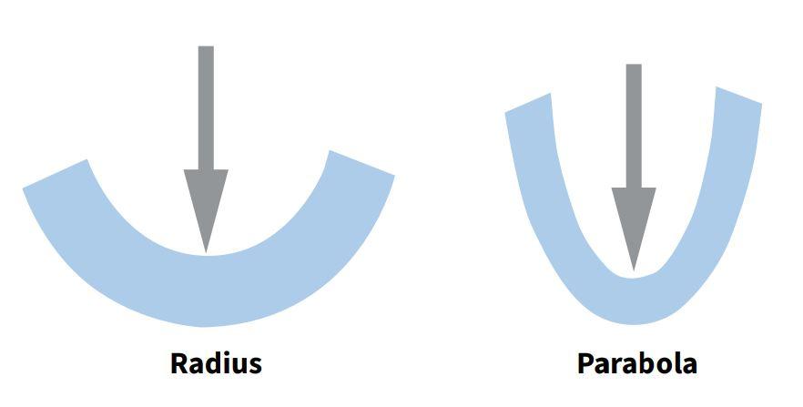
FIGURE 2. Bending sharp creates a parabola at the bend that throws off the bend calculations.
About the Author

About the Publication

subscribe now

The Fabricator is North America's leading magazine for the metal forming and fabricating industry. The magazine delivers the news, technical articles, and case histories that enable fabricators to do their jobs more efficiently. The Fabricator has served the industry since 1970.
start your free subscription- Stay connected from anywhere

Easily access valuable industry resources now with full access to the digital edition of The Fabricator.

Easily access valuable industry resources now with full access to the digital edition of The Welder.

Easily access valuable industry resources now with full access to the digital edition of The Tube and Pipe Journal.

Easily access valuable industry resources now with full access to the digital edition of The Fabricator en Español.
- Podcasting

In this episode of The Fabricator Podcast, Caleb Chamberlain, co-founder and CEO of OSH Cut, discusses his company’s...


