Deep dive into press brake tonnage, Part II: Science behind bending forces
Understanding how an air bend on the press brake turns sharp
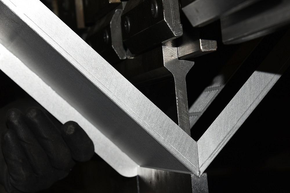
Why and how do bends turn sharp when they do? It has to do with how bending forces affect the workpiece. Getty Images
Last month I described some viable reasons for using ultimate tensile strength rather than yield strength to calculate press brake forming tonnage. While some formulas take yield strength into account, ultimately they’re all based on a material’s tensile strength.
Even under the best of conditions, the forming force we calculate will be an estimate of tonnage. As we learned, there are far too many extenuating circumstances that prevent us from calculating an exact value. Grain direction has an effect, as does the bending speed, the die radius, and others that we discussed last month. And there’s even more that we didn’t cover, including tensile strengths, yield strengths, and material thicknesses that vary widely within a material gauge’s tolerance range, not to mention the differences in material makeup and structure. Nonetheless, we can get a reasonably accurate estimate of the forming force.
That said, why discuss forming pressure calculations if we are discussing sharp bends? How does forming tonnage relate to a sharp bend? For that matter, what is a sharp bend, and why should you even care? Here’s why: The bending force required essentially determines if, when, and where a sharp bend will occur.
What Is a Sharp Bend?
We usually rely on our old rule of thumb: A bend turns sharp when the inside bend radius reaches about 63 percent of the material thickness. But there is perhaps a better way to calculate our “sharp” value.
First, let’s look at what a sharp bend really is. It’s a type of bend where the combination of the punch nose, die opening, and bend length raises the forming tonnage high enough to break the surface of the material, causing a crease on the inside radius of the bend.
That crease is caused by the nose of the punch penetrating the surface of the material being bent. We call that surface area the land area, or land surface area. If the required forming force is great enough, it will push the punch nose into the material, penetrating the material surface (see Figure 1). Creasing the center of the inside radius amplifies how the parts react to material inconsistencies, like variations in thickness, grain direction, and tensile and yield strength.
As the punch nose pierces the sheet surface, all the material variations that commonly cause minor bend angle changes will increase, and the bend angle will become even more unpredictable than usual. All this will affect your linear dimensions, because of issues related to gauging off fluctuating bend angles. The “sharper” the relationship of the punch nose radius to the material thickness, the more pronounced the effect becomes.
Forming Method Factors
When coining, we use a very small punch radius. Producing a very sharp bend radius is the goal, and it’s established by forcing the punch nose radius to less than the material thickness, stamping the radius, and forcing the angle. In bottom bending, the radius still is stamped and the angle is set by the process, so again, there is no issue with the bend angle or dimensions once they’re set.
In air bending, or air forming, we float the radius, which forms as a percentage of the die opening. It is in air forming where we need to concern ourselves with the sharp bend. Because air forming is the most prevalent forming process performed on a press brake today, sound knowledge of the sharp bend is a necessity for operators and engineers alike.
Predicting the Sharp Bend
For many years I have used a simple rule of thumb, that being a bend radius would turn sharp when the inside bend radius was 63 percent of the material thickness, at least in cold-rolled steel. It’s a value arrived at after years of observation on the shop floor.
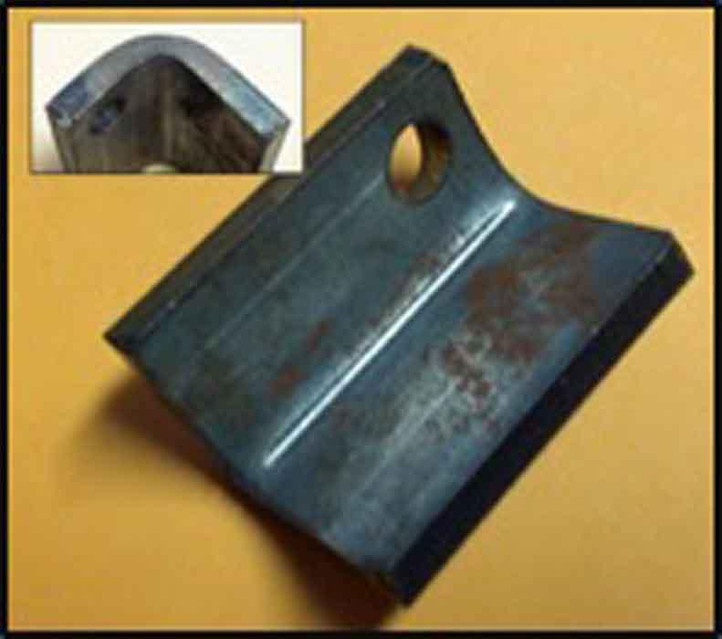
Figure 1
A sharp bend occurs when the punch tip creases the inside bend radius.
The 63 percent became the default rule of thumb for predicting a sharp bend. But when we applied the concept to material types other than cold-rolled mild steel, 63 percent was no longer valid, so we used a fudge factor. But the fudge factor, too, was based mainly on experience.
In past columns I’ve described calculations that go beyond the rule of thumb and refine our sharp bend estimation. Specifically, I compared the tonnage required to punch a hole in a given piece of material to the load required to form the same part. If the forming tonnage exceeded the tonnage required to punch a hole (or the “piercing” tonnage), then the bend would be sharp. (For more on this and the formulas used, see “How an air bend turns sharp,” archived at www.thefabricator.com.)
A bit of a disclaimer here: Like the tonnage calculations, this piercing tonnage estimation is based on material tensile strength. At the same time, the moment of bending is based on yield strength, the point at which the material’s elastic properties become plastic. I borrowed that piercing tonnage formula from the punching arena. It turns out that this is a bit of an apples-to-oranges comparison. Then again, it’s only a rule of thumb, and it does help us avoid most sharp bends.
But there is a better way. Let’s start by analyzing what goes on during a sharp bend. To do this, we need to look at the calculation for land surface area, or area of contact between the punch tip and material as the bend begins.
Defining the Land Area
You might assume that the width of the land area is the punch radius, but in truth, this does not reflect what’s going on during an air bend at the “moment of bending.” If we were to measure the curved area at the bottom of, say, a 0.062-in.-radius punch tip, the width value would not equal 0.062 in.
Instead, we need to find the actual area of contact between the metal and punch nose—specifically, the arc length along the radius that interacts with material at the moment of bending. You’ll see the calculation for arc length incorporated in the land surface area equation in the next section.
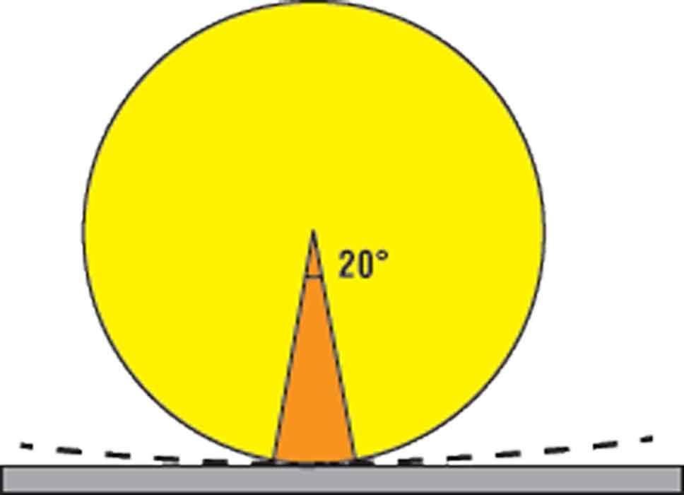
To calculate arc length, we need the degrees of punch-tip contact at the moment of bending (see Figure 2). For our purposes, we use 20 degrees of contact, which is consistent with the moment of bending. Note that this moment of bending is not the maximum forming load. Peak tonnage occurs at approximately 60 degrees into the external bend angle.
Calculating Sharp From Yield Strength
To calculate where a sharp bend begins, we need to compile the following:
Material thickness (Mt) in inches
Material tensile strength (Ts) in PSI

Figure 2
The circle represents the punch tip, and the red area shows the degrees of contact the tip makes just as the metal starts to bend, as represented by the dotted line.Material yield strength (Ys) in PSI
Die opening (Dw), width of the opening in inches
Punch nose radius (Pr) in inches
Bend length (BL) in inches
The contact angle (Ca)
Again, for our purposes, we can use a 20-degree constant for the contact angle (Ca). Once we have all this, we then calculate the following:
Tensile ratio (Tr) = Current material tensile strength in PSI/60,000
Rf = Required forming tonnage in PSI
Df = Force required to deform
Ls = Land surface area
Rf = 575 × Mt2 × Tr/Dw/12 × BL
Ls = [(2π × Pr)/360] × Ca × BL
Df = Ys × Ls/2,000
If the tonnage to deform (Df) is less than the required forming tonnage (Rf), the bend is sharp. If Df is greater than Rf, you have a radius bend. Incidentally, if you visit TheArtofPressBrake.com, you will find a sharp bend calculator under the tool tab on the menu bar. It computes the math discussed here. Feel free to check it out—it’s free!
Sharp Bends and the 20 Percent Rule
The naturally floated radius in an air-bent part forms as a percentage of the die width. We call this the “20 percent rule,” but it’s only a title, as the percentage changes with the material type. Our baseline material is 60,000-PSI mild steel, which forms a radius at about 16 percent of the die opening, give or take a few percentage points.
To estimate the floated radius for the material you’re bending, multiply the die opening by the correct material percentage:
Air bent radius = [0.16 × (Material tensile strength in PSI/60,000)] × Dw
Again, this gives you a starting point. Depending on your material and other variables, you might have to adjust your percentage a bit up or down. This is something you’ll be able to define over time.
Nonetheless, even a large floated radius bend can still be a sharp bend if circumstances are right, and this is where those sharp bend calculations can help. Avoiding a sharp bend is about not penetrating the surface structure of the material.
As an aside, do not use the nose radius of the punch in your bend calculations. Instead, use the value of the floated bend radius. Failure to do so will give you the wrong bend deduction value.
Not Perfect, but Closer
These sharp bend calculations still aren’t perfect. They get a little shaky at the extreme ends of yield-to-tensile-strength ratios. We’re still working on that one.
Regardless, delving into this kind of detail at least gives us an understanding of what’s going on when a bend turns sharp. Understanding how this concept applies to real-life situations allows us to deploy countermeasures and make projects better, experience fewer issues, and substantially reduce or even eliminate operator aggravation.
Steve Benson is a member and former chair of the Precision Sheet Metal Technology Council of the Fabricators & Manufacturers Association International®. He is the president of ASMA LLC, steve@theartofpressbrake.com. Benson also conducts FMA’s Precision Press Brake Certificate Program, which is held at locations across the country. For more information, visit fmanet.org/training, or call 888-394-4362. The author’s latest book, Bending Basics, is now available at the FMA bookstore, fmanet.org/store.
About the Author

About the Publication

subscribe now

The Fabricator is North America's leading magazine for the metal forming and fabricating industry. The magazine delivers the news, technical articles, and case histories that enable fabricators to do their jobs more efficiently. The Fabricator has served the industry since 1970.
start your free subscription- Stay connected from anywhere

Easily access valuable industry resources now with full access to the digital edition of The Fabricator.

Easily access valuable industry resources now with full access to the digital edition of The Welder.

Easily access valuable industry resources now with full access to the digital edition of The Tube and Pipe Journal.

Easily access valuable industry resources now with full access to the digital edition of The Fabricator en Español.
- Podcasting

Patrick Brunken, VP of Addison Machine Engineering, joins The Fabricator Podcast to talk about the tube and pipe...