


Professor and Director
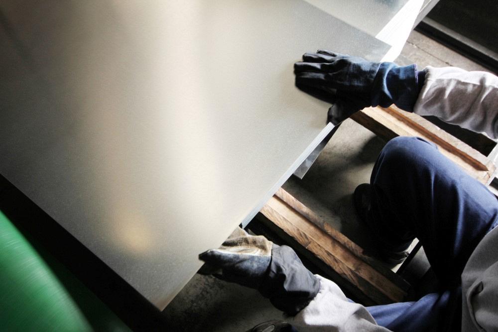
Getty Images
Editor’s Note: Just as the jersey number of a great ball player is retired when he or she does, we are retiring “R&D Update” with the great Dr. Taylan Altan, who retired this year.
Welcome to “Engineering Angle,” our newest column. This column is engineered to deep dive into engineering research as well as its applications for real-world metal forming processes. Dr. Sergey F. Golovashchenko, professor and director Center of Advanced Manufacturing and Materials, Mechanical Engineering Department at the School of Engineering and Computer Science, Oakland University, will provide the white paper research and content. You may recall reading a previous article by Dr. Golovashchenko in the May issue of STAMPING Journal.
The use of lightweight materials such as aluminum alloys and advanced high-strength steels in stamped components provides significant weight reduction in the final product, and those materials are growing in demand as lightweighting increases in the automotive industry. Self-piercing riveting (SPR) is one method used for joining these lightweight materials to others with different chemical compositions and mechanical properties, such as steel sheets to aluminum alloy sheets. SPR can be used to join nonmetallic sheets to metal sheets as well.
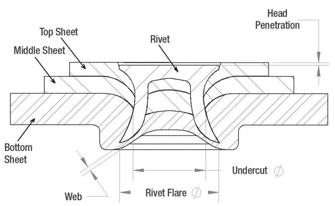
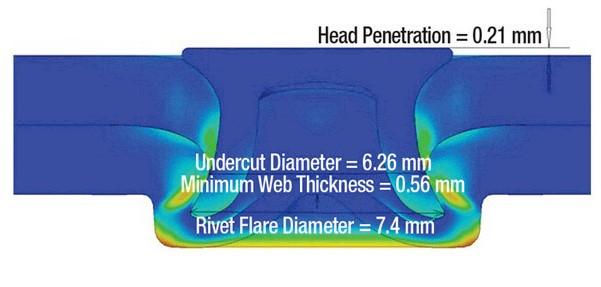
Figure 1 illustrates the critical characteristics of the joint, which are the rivet head penetration, the difference between the rivet undercut diameter and the rivet flare diameter, and the residual web thickness of the bottom riveted sheet.
SPR joints can be evaluated by analyzing their cross sections prepared as metallographic mounts. While this method is effective, it is time-consuming and involves high costs for labor and the necessary riveting and lab equipment. To help decrease this cost and shorten the development time, researchers at Oakland University’s Center of Advanced Manufacturing and Materials have evaluated the use of finite element analysis (FEA) models for developing the riveted cross section and for measuring the required critical characteristics. The challenge with this technique is to identify the model input parameters properly. This study presents a method for identifying the flow curve for the rivet, the flow curves for the riveted sheets in the range of strain observed in the SPR joining process, fracture strain of the riveted sheets, and coefficients of friction (COF) for all contacting surfaces.
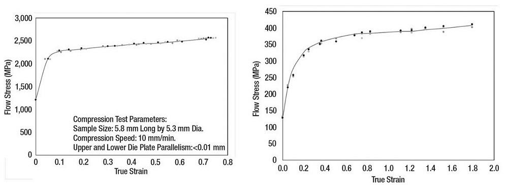
SPR rivets typically are made of AISI 10B35 (boron steel). The researchers generated the flow curve for this material (see Figure 2) by compressing 5.8-mm-long and 5.3-mm-dia. samples from actual forged and heat-treated rivets. To minimize the effect of friction during the compression test, they lubricated the top and the bottom surfaces of the tested samples and the compression tooling with molybdenum-disulfide lubricant and performed the tests incrementally, applying lubrication after each compression step.
AA6111-T4 aluminum alloys (see Figure 2) often are used for outer skin panel applications. The SPR process causes these sheet materials to separate and severely deform. True strains depend on the riveting conditions and riveting anvil design, and in most cases, true strains reach order-of-magnitude larger values compared to uniform elongation in tensile testing. The researchers used the incremental cold-rolling process to prestrain sheets, then prepared dogbone samples and tensile-tested them along the rolling direction.
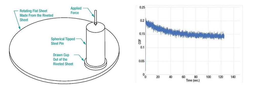
The SPR process involves several contacting surfaces with different contacting conditions. Researchers chose a pin-on-disc test to study the COF (see Figure 3). The proposed new concept was to form a cap from the sheet material that would be dressed on the pin in a simple sheet metal forming tool, with the pin acting as a punch.
They performed the friction test using a drawn cup on the pin side of the test and a flat disc on the disc side of the testing apparatus. The lower disc rotated at 5 RPM and an equivalent linear velocity of 0.8 MPM. All tests also ran until a perceived steady-state COF graph was observed.
Employing this testing method, the researchers determined COF values for the two riveting sheets in contact. Figure 3 shows the graph of the COF for aluminum alloy AA6111-T4 in contact with similar AA6111-T4 sheet. To determine the COF between the riveting anvil and the riveted sheet, they used a pin manufactured with a spherical tip surface on the end that contacted the AA6111-T4 riveted sheet—the same machining operation used for producing the riveting anvils.
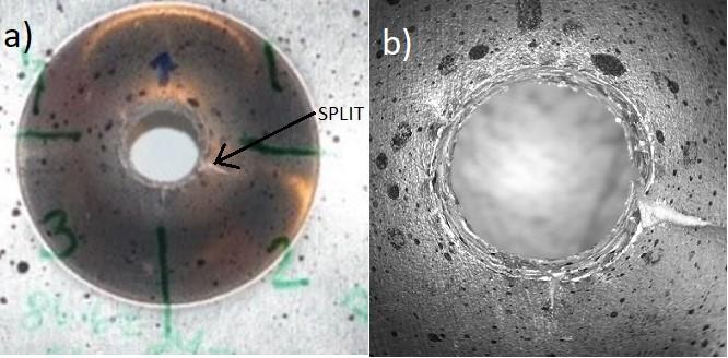
Cockcroft and Latham's criterion is practical and easy to use for SPR processes. To define the fracture strain necessary to use this criterion employing Simufact software, researchers performed a hole expansion test (HET) on a Detroit ductility tester with a 20-mm-dia. hemispherical punch polished to a 0.1-μm surface finish.
The sheet metal specimens used for this test were lubricated with molybdenum disulfide where they contacted the punch. The specimens were prepared with a 5-mm-dia. hole centered above the pole of the punch. Holes in the blanks were prepared by a set of drilling and reaming operations for minimal burr creation.
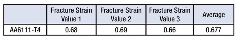
An important aspect of determining the fracture strain using HET is to measure it as close as possible to the edge of the hole and the initiation of fracture. To achieve this, the researchers coupled the test with a spackling measuring technique proposed by Golovashchenko (see Figure 4). Figure 5 shows the fracture strain measured for AA6111-T4 aluminum alloy sheet.
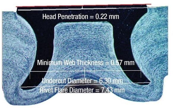
The FEA model was validated for two AA6111-T4 sheets riveted to each other. The input parameters were introduced into the Simufact software FEA model, which produced a 2D result that the researchers compared to the experimentally validated SPR joint cross section. The critical characteristics were measured and compared between the FEA-predicted and experimentally validated results (see Figures 6 and 7). As shown, the two cross sections correlate closely.
References:
M. G. Cockcroft and D. J. Latham, “Ductility and the Workability of Metals,” Journal of the Institute of Metals, Vol. 96 (1968), pp. 33-39.
S. Golovashchenko, “Method of measuring localized strains in sheet metal stampings,” The United States Patent Application publication 20180335296, November 22, 2018.

Professor and Director
Oakland University Center of Advanced Manufacturing and Materials (CAMM)


The Fabricator is North America's leading magazine for the metal forming and fabricating industry. The magazine delivers the news, technical articles, and case histories that enable fabricators to do their jobs more efficiently. The Fabricator has served the industry since 1970.
start your free subscription
Easily access valuable industry resources now with full access to the digital edition of The Fabricator.

Easily access valuable industry resources now with full access to the digital edition of The Welder.

Easily access valuable industry resources now with full access to the digital edition of The Tube and Pipe Journal.

Easily access valuable industry resources now with full access to the digital edition of The Fabricator en Español.
Patrick Brunken, VP of Addison Machine Engineering, joins The Fabricator Podcast to talk about the tube and pipe...


