


Have problems calculating the flat in sheet metal bending?
Bend radius production depends on the press brake tooling; CAD software probably isn’t to blame
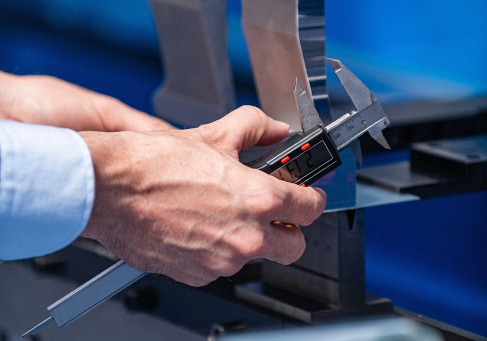
Before calling CAD tech support, measure the formed part’s inside bend radius. If you get the radius wrong, your bend calculations will fall apart. Getty Images
I get many letters that ask this same fundamental question: Our flat blanks never seem to work out correctly. We make dozens of trips between engineering, programming, and the shop floor before getting a working flat blank.
We have talked many times with the CAD system representatives and programmers. They assure us that the program is operating correctly, but we still can’t get the numbers to work out. They tell us that we can adjust some of the numbers for k-factors, bend allowance, and bend deduction. But a bend deduction requires a bend allowance, and the bend allowance requires a k-factor. The k-factor is usually an arbitrary value, and no one seems to know how to calculate a k-factor anyway. For that matter, no one can tell us where the k-factor is even applied within the empirical formulas.
The letters all end pretty much the same way: What are we missing here? If the CAD system is working correctly, why are the blanks always incorrect?
First, let me say that the CAD people are correct when they tell you the formulas are functioning the way they should be. However, their default settings may need to be adjusted somewhat based on the realities of your shop practices.
Ninety-nine percent of the time, the part design and shop practices are causing the problems. Where should you start? Let’s begin with the terminology, as so much of it is misused.
Terminology
While I often pontificate on the topic of trade-specific language and its misuse, it bears repeating. All too often one person’s k-factor is another’s bend allowance and another’s bend deduction. People use these terms interchangeably, which is a big mistake. Each has a precise meaning. Someone tries to explain things using the wrong language with the wrong meaning to someone who interprets (often incorrectly) what’s being said—I’m sure that you can see the problem here.
Several terms describe the heart of any bending operation (see Figure 1). One is the neutral axis, which is a theoretical area within the bend that goes through no change during the forming process; it neither expands nor compresses. It does, however, change location, which is the root cause of bend elongation.
A k-factor is a multiplier that calculates the location of the newly relocated neutral axis within the material thickness after forming. A k-factor is never greater than 50% as compression on the inside of the bend cannot exceed the expansion on the outside of the bend. (For a deep dive into the k-factor, check out “Analyzing the k-factor in sheet metal bending.”)
You’ll need the k-factor to calculate the bend allowance (BA), or the distance around the bend at the neutral axis. You can calculate it using this empirical formula, which incorporates the common k-factor of 0.4468:
BA = [(0.017453 × Inside bend radius) + (0.0078 × Material thickness)] × Degrees of bend angle on the outside of the bend
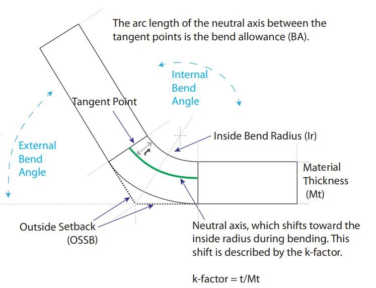
FIGURE 1. Several terms are at the heart of any sheet metal bending operation, including the neutral axis, inside bend radius, outside setback (OSSB), and bend allowance (BA). You calculate the bend deduction by doubling the OSSB and subtracting the BA.
The k-factor in this formula is in the 0.0078 figure: 0.0078 = (π/180) × k-factor. If you want to change the k-factor from the default of 0.4468, you can incorporate it in this part of the equation. Also note that the BA formula always uses the angle as calculated from the outside of the bend—that is, the external angle, as shown in Figure 1.
Figure 1 also shows the outside setback (OSSB), casually called a “setback,” which is calculated using this equation (it’s common practice here to use the external bend angle):
OSSB = [Tangent (1/2 the degrees of bend angle)] × (Mt + Ir)
The OSSB is the distance from the tangent point of the flat and bend radius to the apex of the bend, as measured on the outside of the bend. As Figure 1 shows, there is one setback for each axis.
Finally, the bend deduction (BD) is the difference between twice the OSSB and the BA: (OSSB × 2) - BA. Both the BD and BA are used to compensate for the elongation of the part during forming. When you bend a piece of metal, the piece elongates (gets bigger), so your flat blank needs to be smaller than the sum of the flanges and combined overall dimensions after forming.
You Know the Terms—Now What?
You can apply all this in two different ways to your flat pattern layout. One way subtracts the BD from the totals of the outside dimensions; the other adds the BA to the total of the inside dimensions. Both will give you functionally the same result.
Figure 2 illustrates this concept. X and Y are the two leg (or “flat”) dimensions, as measured from the edge to the tangent point of the radius (to see where the tangent point is, check out Figure 1). The excluded area between the flats is the BA. The sum of X1 and Y1 is the total outside dimension. The BA is added to the X1 and Y2 dimensions (BA + X1 + Y1) and the BD (think “deduct”) is subtracted from the sum of X and Y: (X + Y) - BD.
Figure 3 shows how this concept is applied. The part bent to 90 degrees has a total outside dimension of 5 in.; the vertical leg is 2 in., the horizontal leg is 3 in. Again, metal elongates when it’s bent, so the flat blank needs to be less than 5 in. long.
These graphics are perfect examples of why it is essential that you all speak the same trade language. A k-factor is not a bend allowance, and a bend allowance is not a bend deduction.
The Bend Radius
The values for k-factor, BA, and BD are all derived from the final bend radius in the part—and what bend radius you can produce on the press brake will depend on the tooling you have in the shop. If you’re air bending, your inside radius forms as a percentage of your die opening. If you’re bottoming or coining, the punch nose radius determines the inside bend radius.
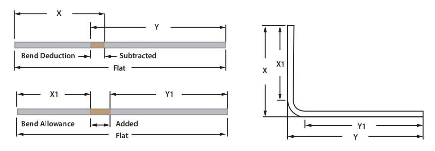
FIGURE 2. The bend allowance is added to the total inside dimension, as measured to the tangent of the bend (X1 and Y1), while the bend deduction is subtracted from the sum of the outside dimensions (X and Y).
If you get this wrong, your flat parts are not going to work out for you after forming. Remember, the bend radius is the heart of any bending operation and should always be your primary concern; it’s what all your calculations are based on and how you can achieve the results you want on the shop floor.
Before you start questioning the CAD provider’s technical staff or making changes to your CAD system on your own, pay attention to the inside radius. First, make sure your brake operators are checking the inside radius. Standard radius gauges aren’t the best option, either, as they come only in standard sizes: 1/64, 1/32, 1/16 in., and so on. These would be fine in a bottoming or coining operation as the bend radius is stamped into the part. But in air forming, the inside radius is produced as a percentage of the die opening; it “floats” and is the reason many shops use gauge pins or even custom, laser-cut radius gauges to check the inside bend radius and to make sure the press brake operator is producing the inside bend radius as called for by the design. When the values for the inside radius are met, the flat should also work.
Go to the Shop Floor
If you have ever attended one of my seminars, you have heard me make this statement: “Go to the shop floor and tell your operators that you are not here to judge them. You’re here for information, that being which methods of forming they use with which material types.” Also, get a list of the tooling they have available and then design around those parameters. I think you will find that your parts work out, and there is no need to adjust your CAD system, though that could still be an option if needed.
One last thing: Let the operators know what toolset you designed this part to be formed with and be adamant that they follow those instructions. The toolset, material, and method of forming determine the inside bend radius. Get that wrong, and you’ll have trouble with all the calculations that follow.
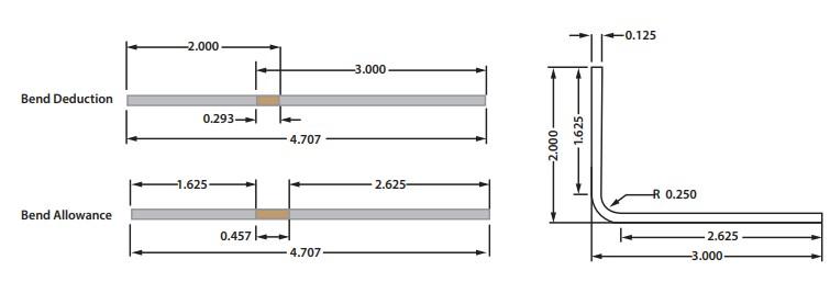
FIGURE 3. This shows how the bend deduction and bend allowance are applied. The total outside dimension after forming is 5 in. Because metal elongates during bending, the flat blank must be less than 5 in.
About the Author

About the Publication

subscribe now

The Fabricator is North America's leading magazine for the metal forming and fabricating industry. The magazine delivers the news, technical articles, and case histories that enable fabricators to do their jobs more efficiently. The Fabricator has served the industry since 1970.
start your free subscription- Stay connected from anywhere

Easily access valuable industry resources now with full access to the digital edition of The Fabricator.

Easily access valuable industry resources now with full access to the digital edition of The Welder.

Easily access valuable industry resources now with full access to the digital edition of The Tube and Pipe Journal.

Easily access valuable industry resources now with full access to the digital edition of The Fabricator en Español.
- Podcasting

In this episode of The Fabricator Podcast, Caleb Chamberlain, co-founder and CEO of OSH Cut, discusses his company’s...


