


Press brake considerations for hemming operations, tooling, side thrust, and more
Metal bending guru Steve Benson catches up on reader emails

Press brake guru Steve Benson catches up on reader emails to answer questions about hemming and bend calculations. Getty Images
I receive many emails every month, and I wish I had the time to answer all of them. But alas, there is not enough time in the day to get it all done. For this month’s column, I have compiled a few emails that I believe my regular readers will find useful. On that note, let’s get started with questions related to layout.
Hemming up Allowances and Deductions
Question: I first would like to say you write amazing articles. I find them extremely helpful. I have been battling out a kink in our CAD software and cannot seem to find a solution. I am working on creating a blank length for hems, but the software always seems to take an extra bend allowance. Our brake operator tells me not to take a bend allowance for hems, so I set the CAD software to the absolute minimum (0.008 in.) for the allowance—yet my blank still comes up short.
For instance, I have a piece of 16-ga. 304 stainless steel with outside dimensions of 2 in. and 1.5 in., with a 0.75-in. hem to the outside. Our brake operator has determined the bend allowance to be 0.117 in. When we add the dimensions and the hem, then subtract the bend allowance (2 + 1.5 + 0.75 - 0.117), we get 4.132 in. for the blank length. My calculations, however, give me a shorter blank length (4.018 in.). All this said, how do we calculate a flat blank for a hem?
Answer: First, let’s clarify a few terms. You mention bend allowance (BA), but you didn’t mention the bend deduction (BD), and I notice you didn’t incorporate the BD for that bend between the 2.0- and 1.5-in. dimensions.
The BA and BD are different and not interchangeable, though either will get you to the same place if you use it correctly. The BA is the distance around the radius as measured at the neutral axis. That number is then added to your outside dimensions to give you your flat blank length. The BD is subtracted from the total of the workpiece’s outside dimensions, one bend deduction per bend.
Figure 1 shows the difference between the two. Just make sure that you are using the correct one. Note that the values for BA and BD may vary from bend to bend depending on the bend angle and final inside radius.
To review your question, you’re working with 0.060-in.-thick 304 stainless steel with one bend and outside dimensions of 2.0 and 1.5 in., along with a 0.75-in. hem on the edge. Again, you didn’t include information about the bend angle and inside bend radius, but to keep things simple, I calculated the numbers assuming you are air forming a 90-degree bend angle over a 0.472-in. die. This gives you a 0.099-in. floated bend radius, calculated using the 20% rule. (For more on the 20% rule, you can review “How to predict an air-formed inside bend radius with precision” by typing the title into the search box at thefabricator.com.)
If a 0.062-in. punch radius bends material over a 0.472-in. die opening, and you achieve a 0.099-in. floated inside bend radius, your BA should be 0.141 in., the outside setback should be 0.125 in., and the bend deduction (BD) should be 0.107 in. You can apply this BD to the bend between the 1.5- and 2.0-in. dimensions. (You can look for the BA and BD formulas in my previous columns, including “The basics of applying bend functions.”)
Next, you need to calculate what to deduct for the hem. Under perfect conditions, deduction factor for a flattened or closed hem (in material less than 0.080 in. thick) is 43% of the material thickness. In this case, that value should be 0.0258 in. With this information, you should be able to perform your flat blank calculations:
- Add your outside dimensions: 2.000 + 1.500 + 0.75 = 4.250 in.
- Subtract the deduction for the hem: 4.250 - 0.0285 = 4.2215
- Subtract the BD for the 90-degree bend: 4.2215 – 0.107 = 4.1145
The 0.017-in. difference between your flat blank value of 4.132 in. and mine at 4.1145 in. can easily be explained by the fact that hemming is very operator-dependent. What do I mean by that? Well, if the operator hits the flattening portion of the bending process harder, you will get a longer flange. If the operator does not hit the flange hard enough, the flange ends up being shorter.
The Die Opening and Punch Radius in Air Bending
Question: We have a bending application in which we form a variety of sheet metal, from 20-ga. stainless steel to 10-ga. prepainted material. We have a press brake with automated tool adjusting, with an adjustable V die on the bottom and self-positioning segmented punches on top. Unfortunately, we made a mistake and ordered punches with a tip radius of 0.063 in.
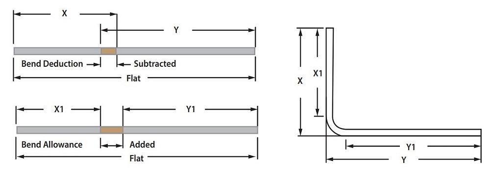
FIGURE 1. This shows how bend deductions (BD) and bend allowances (BA) are applied.
We are struggling with getting our flange lengths to be consistent on the first part. Some have suggested that our CAD software is using the wrong calculations, but our software company looked at the issue and said we are good. Could it be the press brake machine’s software? Or are we overthinking this? Is it simply a common BA adjustment, or could we get new punches with a stock 0.032-in. radius to help? Any information or suggestions would be greatly appreciated.
Answer: I’ll first address your comment about buying the wrong punch radius. Considering the type of machine you have, I assume you are air forming. This leads me to a couple of questions. First, when you send a job to the floor, are you telling operators which die opening the part was designed to be formed over? It makes a big difference.
When you air-form a part, the final inside radius forms as a percentage of the die opening. This is the 20% rule (for more on this, see the first question). The die opening affects the bend radius, which in turn affects both the BA and BD. So, if your calculations incorporate a radius achievable by a die opening that’s different from the die opening the operator is using on the machine, you will have problems.
Suppose the machine uses a die width that’s different than planned. In that case, the machine will achieve an inside bend radius that is different than planned, changing the BA and BD and, ultimately, the part’s formed dimensions.
This leads me to your comment about the punch radius being wrong. Unless you are trying to achieve a different or smaller inside bend radius, the 0.063-in. radius should work fine, and here’s why.
Measure the achieved inside bend radius and make sure it matches the calculated inside bend radius. Is your punch radius really wrong? That depends on what you are trying to achieve. The punch radius should be equal to or less than the floated inside bend radius. If the punch radius is greater than the natural floated bend radius over a given die opening, then the part will take on the punch nose radius. This will again change the inside bend radius and the values you calculated for your BA and BD.
On the other hand, you do not want to use a punch radius that’s too small, which will turn the bend sharp and lead to many other issues. (For more on this, see “How to avoid a sharp bend.”)
Other than those two extremes, the punch nose in an air form is nothing more than a pushing unit and will not affect the BD and BA. Again, the bend radius is developed as a percentage of the die opening, calculated using the 20% rule. Also, make sure that you are applying the terms and values for both the BA and BD correctly, as shown in Figure 1.
Side Thrust and Tonnage for Hemming
Question: I am trying to calculate the maximum side force of a custom hemming tool to ensure that our operators are safe during hemming. Do you have any tips to help me find this?
Answer: Side force or side thrust is difficult to measure and calculate for flattening a hem on a press brake and, for the most part, unnecessary. The real danger is overloading the press brake and upsetting the machine’s ram and bed. Ram and bed upset result in each being permanently bent.
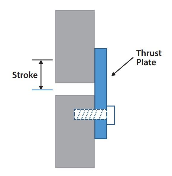
FIGURE 2. A thrust plate on a set of flattening dies ensures the top and bottom tools cannot move in opposite directions.
The press brake normally deflects under load and returns to its original flat position when the load is removed. But exceeding the brake’s load limit will bend the machine components to the point where they no longer return to a flat position. This permanently damages the press brake. For this reason, be sure to factor in your hemming operation in your tonnage calculations. (For more on this, you can check out “The 4 pillars of press brake tonnage.”)
If the flange you are flattening is long enough to flatten, the side thrust, while there, should be minimal. However, if you see that the side thrust seems excessive and you want to limit shifting and twisting of the die set, you can add thrust plates to the die set. A thrust plate is no more than a thick piece of steel added to the bottom tool that extends up past the top tool. The thrust plate mitigates the effects of side thrust and ensures that the top and bottom tools cannot move in opposite directions from each other (see Figure 2).
Keep the Questions Coming
As I noted at the beginning of this column, there are so many questions and so little time to answer them all. If you have sent me a question recently, thank you for your patience.
Regardless, by all means, keep the questions coming. I’ll try to answer them as soon as I can. Until then, I hope that the answers here help those who asked them and others who are facing similar problems.
Precision Press Brake Certificate
This two-day intensive seminar Aug. 8-9 with instructor Steve Benson will teach you the theory and math fundamentals behind the machine to uncover the secrets to working with press brakes. You’ll understand the principles behind quality sheet metal bending through interactive instruction and sample work problems throughout the course. With easy-to-understand exercises, you will learn the skills needed to calculate accurate bend deductions, select the best tooling for the job, and determine the correct v-die opening to avoid part distortion. Visit the event page to learn more.
About the Author

About the Publication

subscribe now

The Fabricator is North America's leading magazine for the metal forming and fabricating industry. The magazine delivers the news, technical articles, and case histories that enable fabricators to do their jobs more efficiently. The Fabricator has served the industry since 1970.
start your free subscription- Stay connected from anywhere

Easily access valuable industry resources now with full access to the digital edition of The Fabricator.

Easily access valuable industry resources now with full access to the digital edition of The Welder.

Easily access valuable industry resources now with full access to the digital edition of The Tube and Pipe Journal.

Easily access valuable industry resources now with full access to the digital edition of The Fabricator en Español.
- Podcasting

In this episode of The Fabricator Podcast, Caleb Chamberlain, co-founder and CEO of OSH Cut, discusses his company’s...
- Trending Articles
1
Capturing, recording equipment inspection data for FMEA

2
Tips for creating sheet metal tubes with perforations

3
Are two heads better than one in fiber laser cutting?

4
Supporting the metal fabricating industry through FMA

5
Omco Solar opens second Alabama manufacturing facility
