- FMA
- The Fabricator
- FABTECH
- Canadian Metalworking
Categories
- Additive Manufacturing
- Aluminum Welding
- Arc Welding
- Assembly and Joining
- Automation and Robotics
- Bending and Forming
- Consumables
- Cutting and Weld Prep
- Electric Vehicles
- En Español
- Finishing
- Hydroforming
- Laser Cutting
- Laser Welding
- Machining
- Manufacturing Software
- Materials Handling
- Metals/Materials
- Oxyfuel Cutting
- Plasma Cutting
- Power Tools
- Punching and Other Holemaking
- Roll Forming
- Safety
- Sawing
- Shearing
- Shop Management
- Testing and Measuring
- Tube and Pipe Fabrication
- Tube and Pipe Production
- Waterjet Cutting
Industry Directory
Webcasts
Podcasts
FAB 40
Advertise
Subscribe
Account Login
Search
Press brake operator struggles with a bend deduction
Why designing metal components around available tools is a good idea
- By Steve Benson
- July 23, 2020
- Article
- Bending and Forming
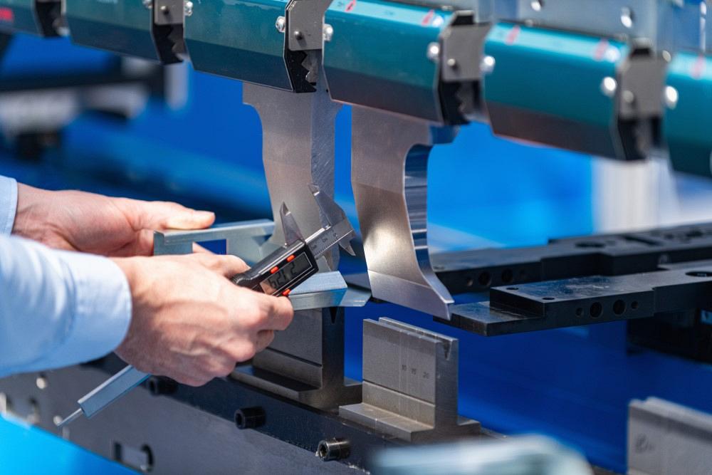
A press brake operator receives a print with an incorrect bend deduction that throws everything off—and spends days trying to make the metal part right. Getty Images
Question: I’ve been trying to figure out what I am doing wrong with the drawing in Figure 1, or perhaps in general. I air-formed three test pieces using a 2-in. die opening.
The 304 stainless steel part is 0.25 in. thick. The die angle is 90 degrees, and the punch is 0.188 in. The print specifies an inside radius of 0.313 in., a bend deduction (BD) of 0.438 in. for the 90-degree bend, and a 0.219-in. BD for the two 45-degree bends. All the bend lengths are 5 in.
When I bend based on these bend lines, the part’s final dimensions are not even close to what I need. So I performed one bend at a time, fine-tuning each, and it looked like all my bend lines were completely changed. Even doing this, I still couldn’t bend the part to within the specified tolerance. Some dimensions were off by as much as 3/16 in. After a couple of days of this, someone else brought another drawing for the same part that specified a 1.5-in. bottom die, a tool that operators apparently had success with previously.
I did some research on the internet and found your articles. They’re extremely useful, but I have a few more questions related to this job. First, should I use the 2-in. or 1.5-in. die? Also, what’s causing some dimensions to be off by as much as 3/16 in.?
Answer: First, let’s tackle the die opening inconsistency. You noted that you were bending this part using a 2-in. die opening, but then another drawing specified a 1.5-in. die opening. This should change your inside bend radius. The larger the die opening, the larger your floated inside bend radius, which in turn will require a change in your BD.
As you know, the radius in air bending forms as a percentage of the die opening. You can calculate the floated inside radius using the 20% rule. Although it’s only a rule of thumb—and the actual percentage changes with material type—it can be reasonably accurate in predicting what the inside radius will be under a given set of circumstances. For your stainless material, air forming should produce an inside radius that’s between 20% and 22% of the die opening.
We’ll start with the median of 21%, which means your 2-in. die opening should float an inside bend radius of about 0.420 in. (2 × 0.21 = 0.420). For that 90-degree bend, the print called for an inside bend radius of 0.313 in., a substantially smaller value. It might not look all that much different visually, even when using a radius gauge; it does take a practiced eye to measure the inside radius correctly sometimes.
This 0.420-in. radius should give you a BD of 0.459 in. for the 90-degree bend—but the print called for a BD of 0.438 in. Clearly, the BD on the original print is off by a small amount. For the 45-degree bends, however, I calculated the BD to be 0.137 in. while the print specified 0.219 in.
This could be at least one source of your problem. It just so happens that 0.219 in. is exactly half of 0.438 in. My guess is someone had a BD calculation for the 90-degree bend, then simply divided the result in half for each 45-degree bend. Unfortunately, that’s not how the bend calculations work. (For a review, see The basics of applying bend functions.
Die Selection
Which die should you use? You begin by calculating a geometrically perfect die opening. For this application, the formula reads as follows: Outside bend radius × 3.429 = Geometrically perfect die opening. You get the outside radius by adding the material thickness (0.25 in.) to the inside radius (0.420 in.). So your perfect die opening should be: 0.67 × 3.429 = 2.297 in.
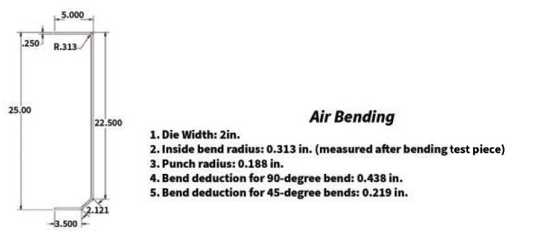
Figure 1
A brake operator struggles to form three 5-in.-long bends—one at 90 degrees and two at 45 degrees—in 0.25-in.-thick stainless steel.
As I have noted in many of my columns, the likelihood of calculating a perfect die opening and finding a die that matches perfectly is slim to none. The idea is to select a die opening as close to perfect as possible. In this case, it would be the 2-in. die you selected.
Also note that the 2-in. die width matches another rule of thumb, the 8x rule: The die opening should be eight times the material thickness, when the inside bend radius is close or equal to the material thickness.
What happens when you switch to a 1.5-in. die opening? Well, everything changes. For that 90-degree bend, that new die opening produces an inside radius of 0.313 and a BD of 0.459 in. For the 45-degrees bends, the inside bend radius is still going to be 0.313 in., but the BD now is 0.133 instead of the 0.219 in. predicted by the original print. That amounts to an error of 0.086 in. per 45-degree bend, or a total of 0.172 in.
Using a 1.5-in. die opening to force the inside radius and achieve the calculated BD can be done. But here’s the bad news: That 1.5-in. die opening is small relative to the material type, the inside bend radius, and the material thickness. This can cause the tonnage to increase to the point of possibly being dangerous. Such overloading can break the tool; embed the tool into the ram and machine bed (sink tonnage); and possibly cause ram upset, or a permanent deflection of the ram and bed. (For more on sink tonnage, see the Four pillars of press brake tonnage.
Another reason that previous runs of this job were able to shrink the radius and make dimensionally acceptable parts is that you are bending with a sharp relationship between the punch radius and material. The forming tonnage for the job has to be more than the force required to deform or pierce the material surface. For more on how to calculate this, search for “How to avoid a sharp bend” in thefabricator.com archive.
You can check out the sharp bend calculator on my website at theartofpressbrake.com. Forming tonnages are based on the material tensile strength, punch nose radius, and die opening; the sharp calculator is based on a material’s yield strength and punch nose radius.
A Follow-up Email
Question: I thought you’d be interested in the new numbers we’re now using. We’re still bending 304 stainless steel over a 2-in. die opening with a 0.188-in.-radius punch. I used 0.4468, the average k-factor you’ve referenced in previous columns. And now we’re using a new BD for the 45-degree bends—0.137 in., much smaller than the 0.219-in. BD previously specified. This of course changed our flat blank dimensions.
All this put our finished part dimensions within tolerance, and we’re now achieving the specified 0.313-in. inside bend radius. One more question: Our result doesn’t seem to follow the 20% rule for air bending. How is our 2-in. die floating a 0.313-in. radius in our 304 stainless material?
Answer: First, congrats—it looks like you found the principal cause of your problem. Your original print was wrong when it came to the 45-degree bends. Sometimes you can cheat a part into tolerance, but it is rare and can be dangerous. It would be better to calculate the numbers correctly the first time. And, of course, always use the correct k-factor when calculating the bend allowance and bend deduction.
Why did your resulting radius not match the prediction made by the 20% rule? First, the rule provides only an estimate and assumes all conditions are perfect, and they rarely are. We all must deal with material property variations and a host of other variables.
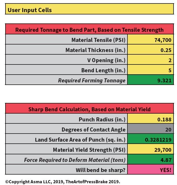
Figure 2
Bending 74,700-PSI-tensile stainless steel with a 0.188-in.-radius punch and 2-in. die opening creates a sharp bend relationship. A larger punch radius should help.
Even so, the 20% rule can get you close enough for many applications, so why is your resulting radius so different? It might be because you’re still bending in a sharp relationship to the material thickness.
Figure 2 shows the results from the sharp bend calculator on my website. As you can see, the tonnage required to form is more than the force required to deform the material, so your bend turns sharp. This probably caused the radius to elongate, shrink, and take on more of a parabola shape.
If you can achieve the desired radius and meet your application requirements—and as long as you’re well within the tonnage capacity of your machine and tooling—bending sharp in this instance might continue to give the results you need. In general, though, bending sharp tends to amplify the effects of other variables, making the process less repeatable.
In your case, a larger punch nose might prevent you from bending sharp; again, you can test alternative punch radii on my sharp bend calculator at www.theartofpressbrake.com. Of course, if your bend is no longer sharp, it would take on the naturally floated inside radius, which would again change your bend calculations and flat blank dimensions.
In an ideal world, parts should be designed around the machines and tools available in the shop. If they aren’t, you can waste a lot of time—and endure a lot of headache—struggling to “make it work” at the press brake.
About the Author

Steve Benson
2952 Doaks Ferry Road N.W.
Salem, OR 97301-4468
503-399-7514
subscribe now

The Fabricator is North America's leading magazine for the metal forming and fabricating industry. The magazine delivers the news, technical articles, and case histories that enable fabricators to do their jobs more efficiently. The Fabricator has served the industry since 1970.
start your free subscription- Stay connected from anywhere

Easily access valuable industry resources now with full access to the digital edition of The Fabricator.

Easily access valuable industry resources now with full access to the digital edition of The Welder.

Easily access valuable industry resources now with full access to the digital edition of The Tube and Pipe Journal.
- Podcasting
- Podcast:
- The Fabricator Podcast
- Published:
- 05/14/2024
- Running Time:
- 62:12
Cameron Adams of Laser Precision, a contract metal fabricator in the Chicago area, joins the podcast to talk...
- Trending Articles
A visit to Automate 2024 reveals the future might be now

Why employee-owned companies make sense in manufacturing

What software automation means for custom fabrication

Majestic Steel Arkansas fully operational

Nucor’s weekly steel price announcement continues to rattle markets
- Industry Events
Laser Welding Certificate Course
- May 7 - August 6, 2024
- Farmington Hills, IL
World-Class Roll Forming Workshop
- June 5 - 6, 2024
- Louisville, KY
Advanced Laser Application Workshop
- June 25 - 27, 2024
- Novi, MI
Precision Press Brake Certificate Course
- July 31 - August 1, 2024
- Elgin,


