


Senior Editor
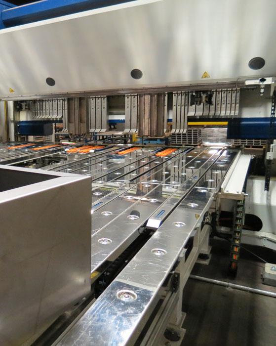
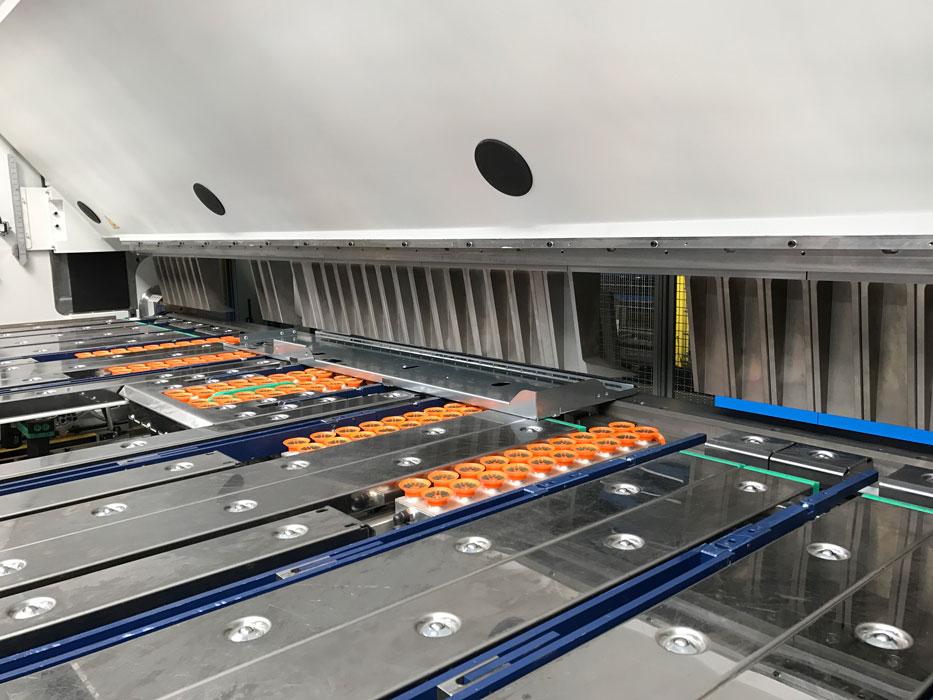
Tall clamping beam tools and suction backgauges (shown in orange) that maneuver the workpiece allow for the efficient folding of tall adjacent flanges. An operator runs this machine standing by a U-shaped backgauge table.
In the early 1990s a sheet metal bending machine started having an increased presence in the U.S. market. The technology wasn’t common stateside, though it had by that time long established itself in Europe. It hit the roofing and architectural fabrication market first, then gradually made its way to the precision and industrial segments.
It didn’t look anything like a press brake, the dominant bending machine of metal fabrication. It also wasn’t a leaf (also called hand, or box and pan) brake, long a staple of roofing and architectural fabricators. But its operation did resemble that of a leaf brake, with a leaf (or beam) rotating upward to bend up (and at first, it was always up) a flange.
Germans called it schwenkbiegemaschinen, translated as “swing bending machine.” American fabricators knew it as the folding machine or, more casually, the folder. So why did the U.S. market evolve so differently from the European market? The answer involves war and Europeans’ affinity for metal roofs.
1950s postwar U.S. looked nothing like postwar Europe. As a new superpower, the U.S. had a massive manufacturing base, built up to feed the war machine, and it had the people needed to do it. On the industrial side of fabrication, the mechanical press brake was becoming the standard. The machines performed bottoming; that is, the punch “bottomed” to the bottom of the V die, forcing the sheet metal against the die angle.
Architectural fabricators didn’t embrace bottoming with the mechanical press brake, and for good reason. Most mechanical brakes used 90-degree dies almost exclusively. If an operator needed to change an angle, he had to change tooling—not very efficient for architectural panels that could call for many different angles in a single part.
Then there was the part marking. Unless a fabricator invested in urethane tape or tools, it couldn’t form a thin, sensitive part without marks or marring, something that architecturally exposed panels demanded. This became even more important as the use of prepainted sheets began to proliferate. Architectural shops produced large, long parts, difficult to handle on a press brake and not the safest to deal with as they whipped up during the bending cycle. For this reason, the hand brake dominated the architectural
Meanwhile, fabricators in Europe were following a very different path. World War II left the continent in tatters, a generation of craftspeople gone. Something needed to fill the gap, and for many fabricators, both on the architectural and industrial side, that something was the metal folder. At first it was similar to a leaf brake, just with a motorized leaf that swung upward and manual backgauges.
“After the war, the rebuilding in Europe began,” said Geoff Stone, CEO of Peachtree City, Ga.-based MetalForming Inc. “In the late 1940s and early 1950s, the Germans started putting motors on [leaf brakes]. A motor would lift the upper beam and another motor would move the bending beam to the correct angle.”
The European standing-seam metal roofing market helped pour more investment into folding technology. A typical folder’s design, with the upper beam slanted backward, gave clearance to fold tall, 90-degree flanges. If bending on just two opposite sides, folders effectively had no flange height limit (beyond the practical limitations of physically moving a piece in and out of the machine). Many workpieces in the architectural world also required hemmed edges, which a folder could form without a tool change.
By the early 1990s folding machines finally started to gain a significant presence in the U.S. architectural fabrication market, a sector that relied a lot on manual labor.
“In the early 1990s we found a market with metal roofers who were essentially upgrading from a hand brake,” Stone recalled. “The folding machine made products seven times faster than a hand brake, so it was a no-brainer. It became a big business.”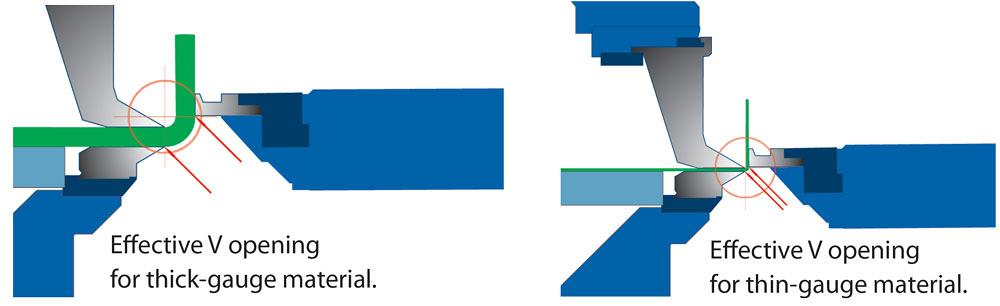
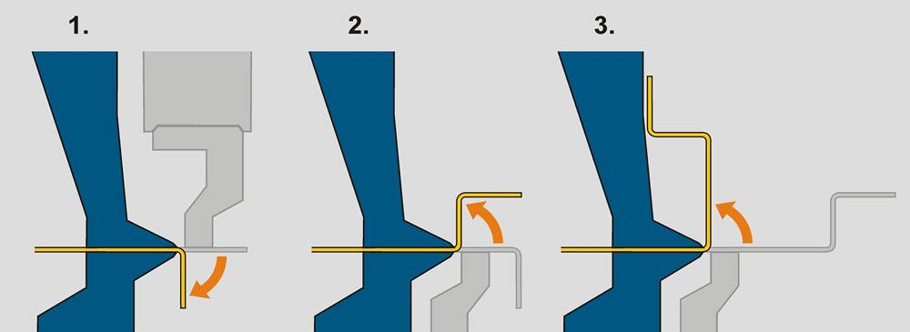
Figure 1
In folding, the distance between the clamping and folding beam contact points is analogous to a V-die opening in a press brake air bending operation. The distance determines the radius and can be adjusted for any material thickness the folding machine is rated to handle. Images courtesy of MetalForming Inc.
“The machine’s design really fit the roofing and architectural market,” added Cindy VanderWaal, department manager, sales, at Roper Whitney, Rockford, Ill. “And, yes, at the time it seemed unbelievable that a roofing company that was making their parts on a hand brake would make a relatively massive investment in a folding machine. But then it happened.”
She added that the math just made sense. “You need three people on a hand brake. You need someone to scribe the part. On a hand brake, you need at least two individuals to manipulate a 10-foot piece. And part No. 1 wasn’t the same as part No. 50.” That inconsistency caused a lot of headaches (and inefficiencies) between those at the architectural fabricator and on the construction site. “Moreover, to make a consistent [bump-formed] radius bend was a true artform.” A folding machine, on the other hand, could bump-form large, complex radii quite readily. “These complex parts were money-makers compared to other ‘me-too’ parts in architectural roofing.”
“There were and still are other related markets, too, including sign-making and HVAC, which have embraced folding technology,” said Mike Smith, president of McMinnville, Tenn.-based Tennsmith (which acquired Roper Whitney in 2011).
This doesn’t mean industrial and precision fabricators didn’t invest in the technology at all. “Folding machines were being sold to the precision market back in the 1990s,” VanderWaal recalled. “But people certainly needed to think differently. This wasn’t a press brake. A folding machine doesn’t require the kind of tool changes that a press brake requires, and people at first were in disbelief.”
As the precision fabrication industry transitioned from bottoming with mechanical press brakes to air bending with hydraulic press brakes and precision-ground tooling, designers got more creative with more bend angles, incremental (bump) bending, and other forming practices that took advantage of the CNC press brake’s flexibility and precision. It just so happened that the metal folder could produce these forms as well, without the need for multiple operators to manipulate a large workpiece during the bend cycle. And in contrast to the tight radius in bottoming and coining, air-bent parts usually had a relatively larger inside bend radius.
“We hit a crossover point,” Stone said. “Folders were able to bend tighter radii, while air bending with hydraulic press brakes created a more open radius.”
“Air bending has really helped the folder’s adoption in the market, because the folder can achieve similar radii as air bending on a press brake,” said Chandler Barden, national sales manager at Cidan Machinery, Peachtree City, Ga.
In the early 2000s servo-mechanical machines started being offered alongside hydraulic machines. “These servo-based systems gave us speed and accuracy, and they allowed us to expand in the precision fabrication arena,” said Bill Kennedy, vice president, RAS Systems LLC, Peachtree City, Ga.
Folding machines aren’t sold in tonnages that describe the maximum forming force they exert. They instead are sold in thickness capacity and lengths, usually up to 0.25-inch carbon steel (though some are even heavier-duty) across a bed length that could be 10 feet, 17.5 ft., or more. Of course, capacity varies by material type. Stainless capacity is typically 60 to 70 percent of the mild steel capacity, and aluminum is about 130 percent.
“We don’t talk in terms of tonnage, though machines have tonnage values when it comes to the clamping force,” Kennedy said, adding that this clamping force determines the maximum material thickness. “You are limited bending shorter lengths of materials thicker [than what the machine is rated for], because the folding machine doesn’t have the clamping force to hold on to it. A folder isn’t a press brake. It’s an entirely different way of forming.”
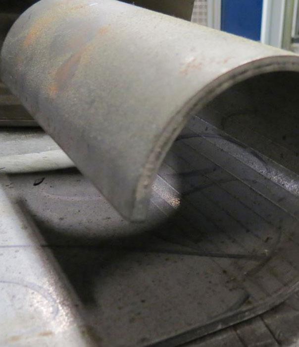
Figure 2
This tight incremental bend in 0.25-in.-thick material was made on a high-thickness-capacity folder. The outside surface has only very faint bend lines.
When air bending, the press brake forms a “floated radius” as a percentage of the die opening. A press brake expert learning how to operate a folding machine could think of the “die opening” as the distance between the contact points of the clamping and folding beam tools (see Figure 1). That distance determines the bend radius. The folding beam tool contacts the outside of the part to commence the bend. The beam swings up and overbends, releases pressure, and the workpiece springs back to the desired angle. According to sources, some folding machines today can form bend angles to plus or minus a half down to a third of a degree.
To form a hem, a folder first bends an edge flange to a small interior angle (past 130 degrees). The clamping beam tool then forms the open or closed hem, with no special tools required.
In a prototype setting, the nature of folding makes flange measurement practical to do before the bend is made. After the material is clamped, the operator measures the protruding metal that will become the flange. As Barden explained, “As long as the operator knows the bend allowance, he should be able to predict the resulting flange length before the bend is made. This really helps efficiency when doing one-off jobs.”
A folding beam on some machines can adjust the point of contact, changing what’s known as the moment of bending. This is how a high-capacity folding machine can bend anything from 30 gauge to 0.25 in. without changing tools. The program identifies what material thickness is being bent, and the lower beam and folding beam adjust to the proper clearances.
David Prokop, executive vice president of MetalForming Inc., described this phenomenon using a protractor metaphor. The point that establishes the center of the circle (as shown by the circles’ crosshairs in Figure 1) is the folding beam’s pivot point. The pencil draws the arc length that the folding beam takes. Close the protractor, and you move the moment of bending closer to the pivot point; this results in the folding beam moving in a short arc length and producing a small radius, optimal for thin material. Open the protractor, and you move the moment of bending away from the pivot point; the folding beam swings in a longer arc length and produces a larger radius, optimal for thicker material.
As Prokop explained, “Driving these two axes [that is, these two points of the protractor] simultaneously gives you the ability to go from 30-gauge to 0.25-in. material with no tool change. Changing the gap between the point and pencil [using the folder’s protractor metaphor] is analogous to changing a V-die opening on a press brake. The adjustments go down to four decimal places.”
Making the bend radius this way works up to a point. Make the gap too big, and the radius collapses a bit and becomes egg-shaped. To avoid this, the folder starts to bend incrementally, like bump bending on a press brake (see Figure 2).
To bend incrementally, two tooling surfaces interact: the clamping beam tool and the folding beam tool. The relationship between those surfaces determines the shape of the radius bend.
“For example, say you need to produce a specific radius bend. The machine knows to move the folding beam to a specific angle,” Kennedy explained. “The upper clamping beam moves up, the backgauge moves the part forward, and as the upper clamping beam moves up and down, it forces the material against the folding beam tool to produce the radius.”
“Folding machines do not use the tonnage that press brakes do, so you’re not going to get those indentations [when bump bending],” he added saying that folding tools also don’t have abrasion points.
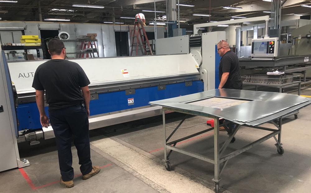
Figure 3
Bending technicians operate a folder from the front. On other machines, an operator stands behind the work area. Photo courtesy of Roper Whitney.
“Some large radii look so smooth, they look like they’ve been formed on a roll former,” Stone said.
“Some heavy-duty folders can bump-form up to ¾-in. material,” Prokop said. “Look at many skid steer buckets out there, and a large percentage of them are being formed on a folder. The backgauge grips the material and feeds it through the bumping process. The bucket looks like it’s been formed with a single-hit die.”
For precision work, modern systems adjust parameters based on the material at hand. “You have to remember that we’re working with sheet metal, and there’s always going to be variability. The intelligence in the system records all the corrections being made when the machine is first implemented,” Stone said. “We bend a few samples of material, and make a few measurements as parts are being bent, and it’s constantly tracking the corrections the operators make. The machine then starts learning what it needs to do to correct automatically for the bending environment to give you the desired result.
“The machine learns,” Stone continued. “It understands what the bend allowance should be, and we use that knowledge to create the flat blank dimension.” He added that once that intelligence is in the control, a folder should be able to make a perfect bend on the first part, no tweaking required.
As Prokop explained, the nature of folding—the fact that the machine forms by applying pressure only to the outside surface of the bend—mitigates material variation effects like thickness and tensile differences. It also makes the process well suited to challenging or sensitive material surfaces, including tread plate, perforated and other hole-intensive material, and prepainted material.
“The folding machine doesn’t touch the inside radius. If that radius is a little bit bigger or smaller because of material property variation, it doesn’t change where the folding beam has to position the flange to achieve the desired angle.”
Depending on the size of the part, the operator can insert the part from the front or back (see Figure 3). When in back, the operator often stands by a J- or U-shaped table, with the horizontal leg of the J or U directly behind the tooling. These shapes make the table long enough to handle long parts but allows the operator to stand close enough to the tools so he can manipulate and slide the work against the backgauges.
When it comes to gauging, a folder has several reference points. It has backgauge fingers that emerge from the backgauge table; the most conventional way to gauge on a folder, these gauge the back edge of the part. The folder also can reference the front edge of the part.
“The folding beam becomes the gauge point when gauging to the front of the machine,” Prokop said, adding that some systems “have fingers that pop out, creating two gauge points for long parts that lack a straight edge.”
Other fingers also can emerge from the table for gauging off of notches or adjacent, previously formed flanges.

Figure 4
Segmented clamping beam tools provide clearance for adjacent flanges as well as sufficient clearance for the return flange. Image courtesy of RAS Systems.
With the right backgauge setting, folders also can handle tapered parts. “It’s a simple process,” Kennedy said. “The gauge fingers have micrometer barrels on them. You simply adjust the two outside fingers, so they bump against the material at a tapered angle.”
A folder’s tools typically can bend any angle and any thickness that the machine is rated for. This doesn’t mean there are no tool changes whatsoever, however. Tool changes usually are needed not because the folder is bending a different material thickness or angle, but instead because it needs to form without colliding with the workpiece.
Using segmented clamping tools to form boxes of different lengths and widths is a prime example. Another is a deep clamping beam tool to handle large return flanges (see Figure 4), analogous to a gooseneck punch on a press brake. Yet another example are corner clamping beam tools with wings that extend to the end of a bend, holding the material underneath previously formed return flanges.
An operator running a heavy-duty folding machine occasionally might change folding beam tools (though not the clamping beam tools) for folding different thicknesses. Other special folding beam tools can help reach tight areas in return flanges.
The operator could also insert a special segmented folding beam tool that approaches the workpiece from an angle, allowing the folder to form 90-degree internal flanges (see Figure 5). Because the folding beam tools are segmented, they can access bends in internal cutouts. And because the tools are angled, the folding beam itself need not swing 90 degrees to make a 90-degree angle; this prevents the beam from colliding with the workpiece.
Some folders today come with automatic tool changes, with mechanized grippers swapping out the clamping beam tools (see Figure 6). Because some machines form deep boxes, they require tall clamping beam tools, more than 19 in. in some cases. These large tools make automatic tool changing a necessity.
Other machines have rotating upper beams, which add tooling flexibility. “One side of the beam has segmented clamping beam tools for making boxes and other four-sided part geometries; and another side having a conventional clamping beam solid tool for making flanges without adjacent bends,” said Barden, adding that machines also can have segmented box tools on both sides of the clamping beam.
Folding machines also can have segmented clamping tools on both the upper and lower beam. Combine this with a height-adjustable backgauge table, and a folding machine can form complex parts, including those that must be gauged off a previously formed negative (downward) bend (see Figure 7).
Sources emphasized that in folding, tool changes are the exception rather than the rule. “We don’t change clamping beam tools for thickness or different bend angles,” Stone said. “We’re only changing them for space,” providing clearance for previously formed flanges.
Another advancement arguably has had a far greater impact in folding than automatic tool changing: the bidirectional, or up-down, folding beam (see Figure 8). Decades ago folding machines’ bending beams swung only upward to create a positive bend. If an operator needed to create a bend in the other direction, he needed to flip the piece. For large pieces this could be time-consuming, and for many it was a major limitation. After all, the primary reason fabricators invested in a folding machine in the first place was to bend large parts.
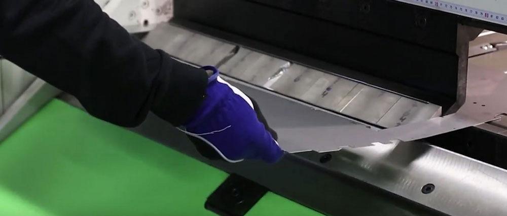
Figure 5
Angled, segmented bending beam tools allow folders to bend 90-degree flanges within interior cutouts in the workpiece. Image courtesy of Cidan Machinery.
The act of up and down bending on a folder is far more complicated than it looks. First, the beam must move outward to avoid colliding with previously formed flanges. Second, its pivot point must change so that the edge of the swing beam’s bending tool contacts the outside of the workpiece in the right place, both above and below the workpiece. Thanks in part to precise servomotors and other advancements within the past decade, the modern folding machine can accomplish this feat quite readily, with no manual intervention.
Regarding automation, sources emphasized the need to look not just at the folding speed or part-to-part time, but the entire folding process, from design to bending to the flow downstream. Having an incredibly fast folding time is fine, but a shop won’t realize the benefit until the non-folding tasks—the programming time, the setup, the feeding of material, and moving the folded part to the next operation—can keep up with the machine. As Eliyahu Goldratt stated in his theory of constraints, any efficiency gain at a non-constraint process is a mirage.
That said, today’s folding machines have a range of automation possibilities. One is to use vacuums in the backgauge fingers that grasp the part and maneuver it from bend to bend on one edge (or one plane) of the part (see Figure 9). The machine is programmed to open the clamp, move the part, close the clamp, and perform each bend. The operator need not spend his days constantly hitting a foot switch for each bend and positioning the part against the backgauge fingers.
“Because the operator is out of the work area and behind a light curtain, the machine does not need to perform its safety stops either, like a pause before the clamping beam pinches the material,” Prokop said. “This speeds the cycle time tremendously.” (Of course, if the operator or anyone, or anything, else breaks the light curtain, the machine stops.)
Beyond this comes further mechanization and robotics. Some systems integrate robotic arms that lift sheets onto a conveyor that in turn carry the sheets to the backgauge table, at which point a mechanized foot moves the workpiece into position against the backgauges. After one edge is formed, the mechanized foot rotates the workpiece for the next bend. Other systems use a pick-and-place robot to rotate the workpieces and place them against the gauges.
“If a machine has a part manipulator on it, the sky’s the limit,” Kennedy said. “You can integrate towers, robots, gantry systems, and other automation. Two things drive this: the fabricator’s required product flow and the floor plan.”
He added that a robot can make sense for the right part mix—say, if it’s lifting and feeding a series of large blanks onto a folder’s backgauge table. “But it’s not always so easy just to adapt a robot to every folding operation. A lot of movement from the robot can actually slow the process down, especially since the folder can move so quickly through small lot sizes.”
“In many cases, shops find it most efficient to use a conveyor to feed the parts to the folder,” Prokop said.
Picture the following automated, unattended folding situation for a high-product-mix environment: A conveyor is positioned near the shakeout and stacking station after the cutting operation. After sorting, a worker places pieces with laser-etched QR codes (or other labels) onto a conveyor, in the order in which they need to be formed. The machine forms the kit of parts sequentially. Suction gauges then push a part through the front of the machine, where a conveyor swings in and carries the formed workpiece on to the next operation. The conveyor then swings out of the way for the next, completely different part.
Besides physical automation, automation of information processing has entered the folding arena as well. This includes offline programming and simulation.
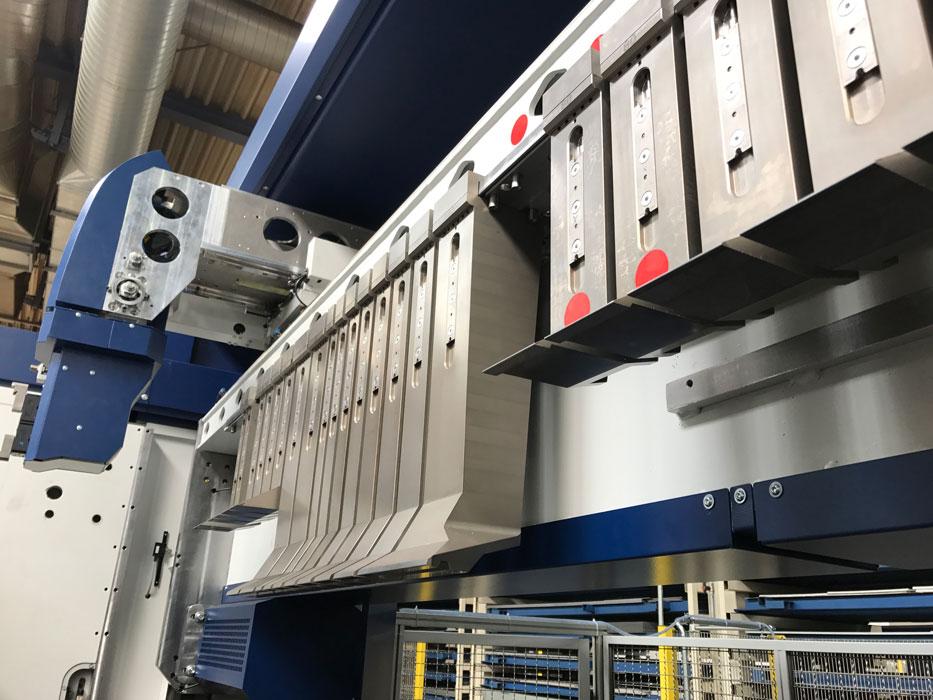
Figure 6
Some folders today come with clamping beam tools that can be changed out automatically. Photo courtesy of MetalForming Inc.
“You can now take a CAD file, a STEP file, or a DXF file and convert it into machine language,” Kennedy said. “Essentially, this allows on-machine programming to go by the wayside. A designer can design a part and then look at a simulation of the machine bending the part, so he can know that it can be made on the machine. He can send the part right to the control, and the operator pulls the part number up. The operator may need to tweak it to account for material variability. But for the most part, all the moves the machine needs to know are there.”
Controls overall have become more user-friendly. “Folders have touchscreen controls now where the operator can program many intricate parts much more quickly than you could years ago,” Smith said.
A folding machine could never replace a press brake entirely. To be folded, a part requires a flat surface for the clamping beam tools to grasp. And sources did point out that folders have limitations when trying to hem thick material.
As with any other sheet metal bending technology, folding does require that a part have a minimum flange length. A folder typically needs a flange to be at least 6 times the material thickness, though some machines working on some part geometries can work with flange lengths down to 3 times material thickness. (Sources emphasized that this is part-dependent.)
When it comes to flexibility, the press brake has major advantages. If a fabricator needs to form a complicated part with uneven surfaces (that is, it wouldn’t lie flat between bends), a press brake may still be the best approach. And aside from a few specialty applications (like bump-folding those skid buckets), for thick plate, a high-tonnage press brake is usually the only option.
“You see shops with folding machines sitting next to press brakes, which are sitting next to panel benders,” Prokop said. “Every machine has its place.”
“Most fabricators have parts that are perfectly suited to run efficiently on the press brake,” Kennedy added, “but then they have some parts that can run so much faster on a folder. The two machines are a perfect marriage, really.”
Every forming option has its pros and cons; it’s the nature of technology in general. But according to sources, when it comes to precision sheet metal forming, the modern fabricator has plenty of choices, and a folding machine is one that shouldn’t be overlooked.
Cidan Machinery, www.cidanmachinery-americas.com
MetalForming Inc., www.metalforming-usa.com

Figure 7
Combine segmented tools and a height-adjustable backgauge table, and a folder can form an upward flange while gauging off a side with a previously formed downward flange. Segmented tools on the lower beam give clearance for a previously formed adjacent flange. Image courtesy of Cidan Machinery.
RAS Systems LLC, www.ras-systems.com
Roper Whitney, www.roperwhitney.com
Tennsmith, www.tennsmith.com


The Fabricator is North America's leading magazine for the metal forming and fabricating industry. The magazine delivers the news, technical articles, and case histories that enable fabricators to do their jobs more efficiently. The Fabricator has served the industry since 1970.
start your free subscription
Easily access valuable industry resources now with full access to the digital edition of The Fabricator.

Easily access valuable industry resources now with full access to the digital edition of The Welder.

Easily access valuable industry resources now with full access to the digital edition of The Tube and Pipe Journal.

Easily access valuable industry resources now with full access to the digital edition of The Fabricator en Español.
In this episode of The Fabricator Podcast, Caleb Chamberlain, co-founder and CEO of OSH Cut, discusses his company’s...


