


Contributing Writer

Editor’s Note: This is the fifth in a series of articles presenting the fundamentals of stamping die design and construction.
Drawing is a metal forming process in which the flow of material over a punch or into a cavity is controlled. In deep drawing, the product’s depth is two or more times greater than its width or diameter.
Deep drawing is used for finished part geometries that require a great deal of form or shape, such as oil filters, pots and pans, cups, and bowls. The process typically requires a semideveloped blank, but certain part shapes can be made using an undeveloped blank.
During the drawing process, some metal stretching occurs as the metal is pulled into the cavity via tension. This can cause the metal to stretch and thin out, but it also can cause it to thicken, as certain part geometries, such as cups, force the blank to squeeze together as it flows into the die.
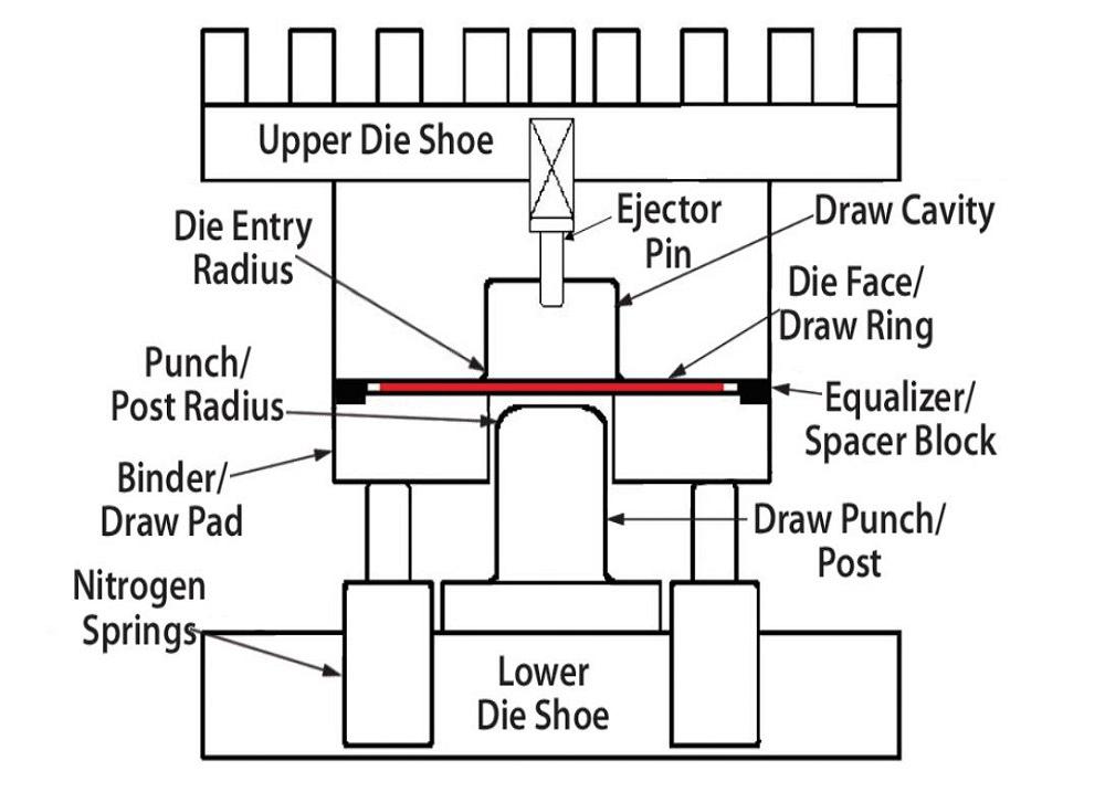
Metal flow into the cavity and over the punch is controlled by a draw pad or binder. It can restrict metal movement to prevent wrinkling as the material flows into the die area (see Figure 1).
Many deep-drawing applications use an engineering concept called draw ratio theory. The drawing ratio is the direct relationship between the diameter of the drawing punch and the size of the blank. If the blank is too large with respect to the punch, too much material will be trapped between the die face and binder. Excessive material between these two surfaces may cause a resistance to metal flow, resulting in excessive stretching, thinning, or potential metal splitting.
To illustrate, imagine I asked you to hold on to the edge of a sheet of paper and then tried to take it from you. Chances are I would be able to pull it free from your fingers. However, if I asked you to clamp that same piece of paper between your palms, the paper would likely tear as I tried to pull it through your hands. This is because you are grasping a much larger surface area when using your palms than when gripping the edge with your fingers.
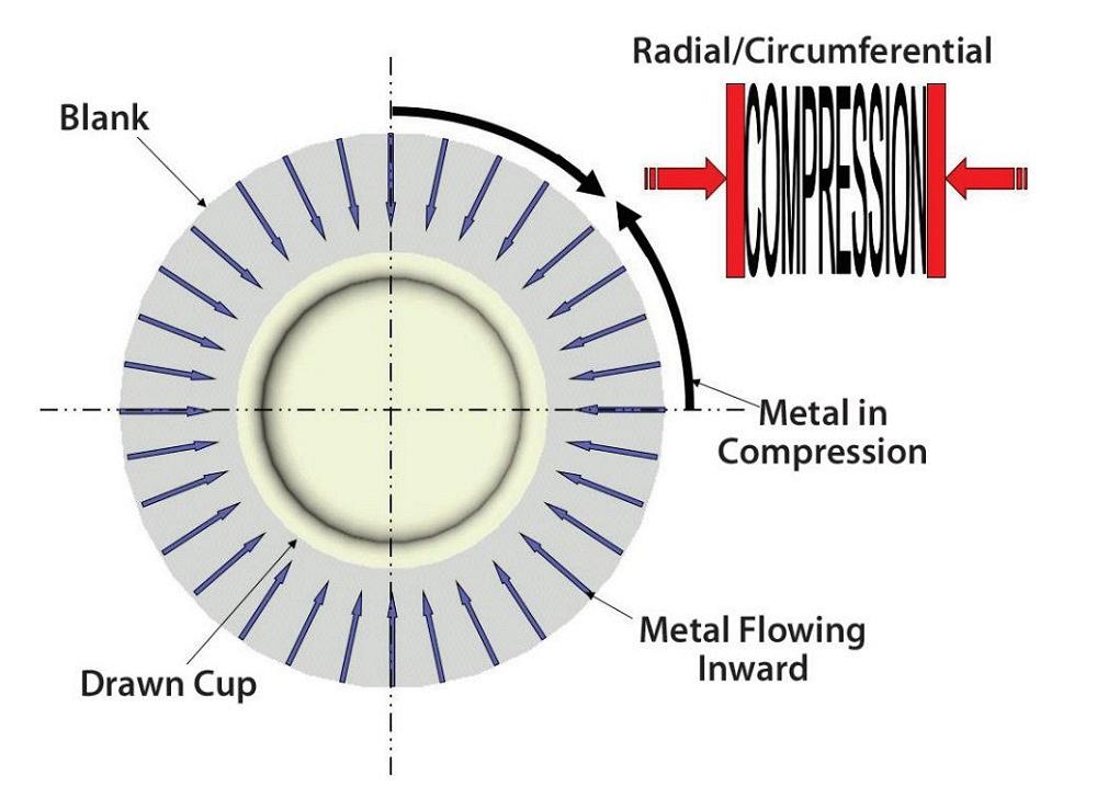
To understand draw ratio theory, you must understand the basics of metal flow. One basic concept is that when a large-diameter blank is forced to flow into a smaller-diameter part, the metal must squeeze together. The squeezing action is typically called compression. If the compression is all the way around a vessel, such as a cup, it is called circumferential compression. Compression created by a corner profile radius is called radial compression. The key point to remember is that metal in compression has a great resistance to flow (see Figure 2).
Because of this resistance, the draw punch must be close enough to the blank edge to minimize the surface area of metal in compression. In simple terms, the draw punch must be an acceptable diameter with respect to the blank diameter. This relationship can be simply defined as the limiting drawing ratio.
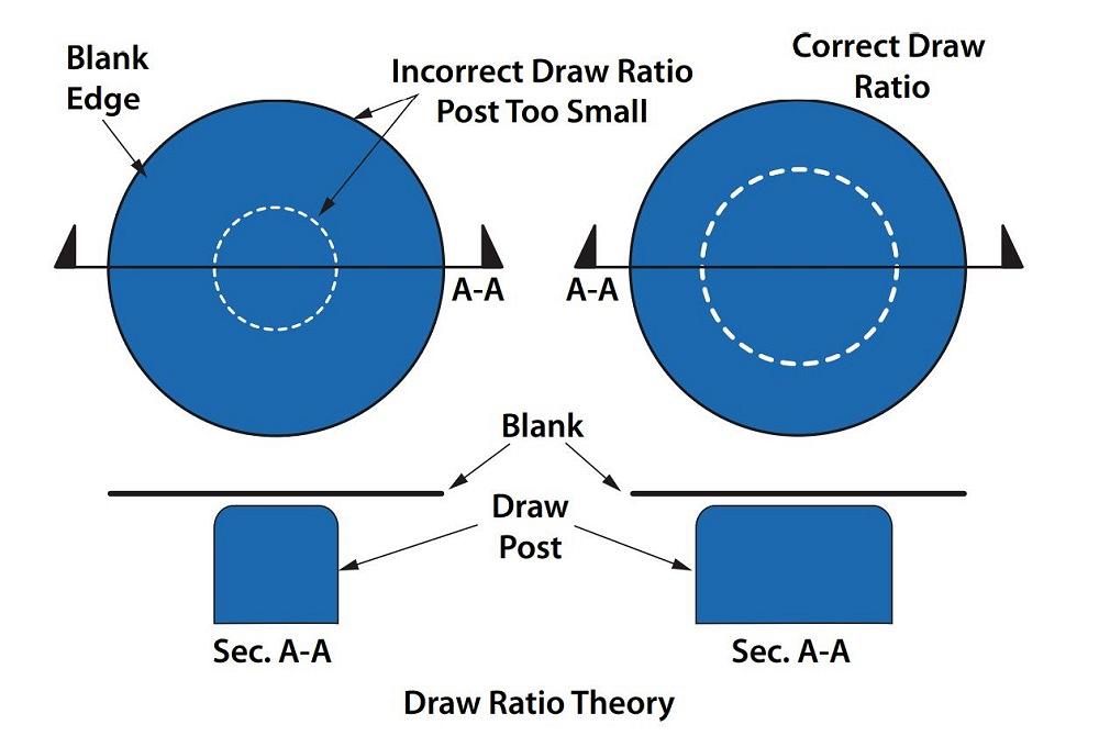
If the draw punch is too far from the blank edge, the metal in compression will not flow, and stretching and possible splitting may result. If the blank is close enough to the punch, the metal will compress and flow inward, resulting in limited stretching and thinning (see Figure 3).
Multiple drawing operations might be required to achieve a very tall part geometry. This process is referred to as draw reduction. A successful draw reduction process requires paying very close attention not only to the relationship between the starting blank and the drawing punch but also the relationships between each drawing operation.


The Fabricator is North America's leading magazine for the metal forming and fabricating industry. The magazine delivers the news, technical articles, and case histories that enable fabricators to do their jobs more efficiently. The Fabricator has served the industry since 1970.
start your free subscription
Easily access valuable industry resources now with full access to the digital edition of The Fabricator.

Easily access valuable industry resources now with full access to the digital edition of The Welder.

Easily access valuable industry resources now with full access to the digital edition of The Tube and Pipe Journal.

Easily access valuable industry resources now with full access to the digital edition of The Fabricator en Español.
In this episode of The Fabricator Podcast, Caleb Chamberlain, co-founder and CEO of OSH Cut, discusses his company’s...


