


Contributing Writer
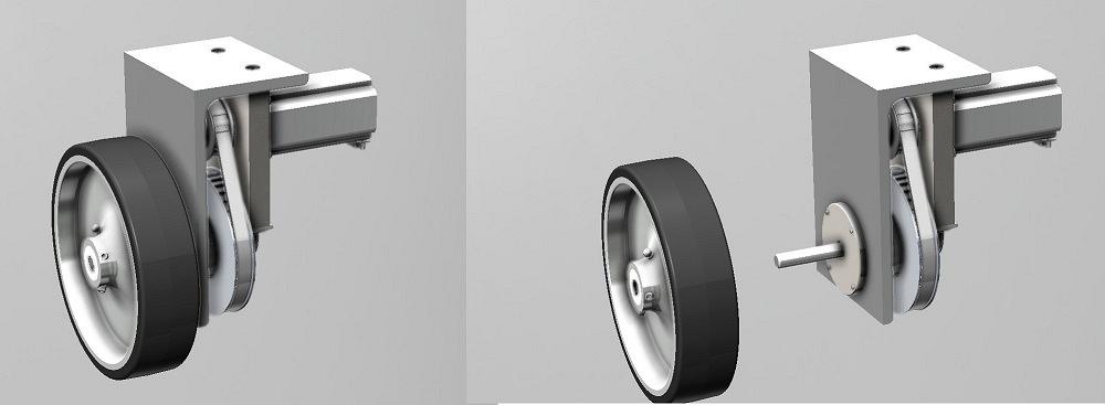
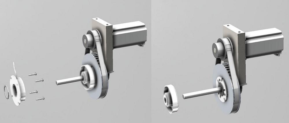
FIGURE 1. A completed drive wheel assembly is shown on the left. The design review starts to the right with the wheel removed from the axle by removing setscrews and a shaft key.
Editor's Note: If you would like to download the 3D CAD files associated with this column, click here.
In the previous episode, a statement of work was prepared for developing a self-propelled cart. The cliffhanger from that episode was to discover off-the-shelf components that could be assembled for a drivetrain. This episode is a progress report presenting a clutch drive that will freewheel when not powered.
The difference between expectation from preparing a statement of work and the results of doing the work represents progress.
Here’s a quick disclaimer: This is an imaginary product being used to demonstrate CAD workflow. A differential wheel drive for a robotic cart serves as an example for decision-making regarding level of detail in purchased items, comparison of downloadable CAD elements to modeling from scratch, and level of complexity in custom-made components.
Steering this cart is accomplished by relative motion between two drive wheels. Mechanically, the same drive assembly is used left and right. One of those two drive assemblies is shown in Figure 1. To start the design review, we can remove the wheel by loosening setscrews and sliding the wheel and shaft key from the axle.
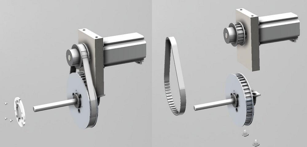
In Figure 2, the disassembly continues. The outer bearing is trapped in its pocket with four screws and an outer cover. The L frame is held to the motor mount with two screws.
The electromagnet for the clutch is held centered with the axle by the outer race of the outer bearing. A retaining clip—visible to the left in Figure 3—keeps the outer bearing from going too far into the electromagnet’s casing. To keep the electromagnet from spinning, four screws clamp it to the L frame.
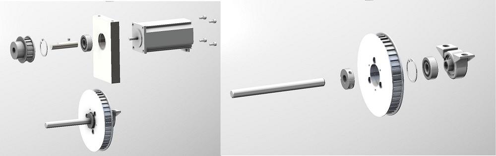
To the right in Figure 3, the clutch torque shell and its shaft key now can slide off of the axle. This torque shell is half of the friction pad pair for the clutch. It is keyed to rotate with the shaft. It is trapped in place along the shaft by the outer bearing and a shaft collar.The other half of the friction pad pair for the clutch is held in place with three screws, seen to the left in Figure 4. These screws pass through an iron pole plate and clamp the friction pad to the timing pulley. The electromagnet pulls the friction pads together. The rotating pulley forces the clutch shell to turn, which forces the axle to turn. This friction pad is centered on the axle and pulley by the outer race of the pulley’s bearing.
The motor assembly with the 16-tooth pulley is separated from the 40-tooth pulley assembly by removing two screws, visible to the right in Figure 4.
The motor assembly, shown exploded in Figure 5, features a bearing-mounted shaft to take the load of belt tensioning off the motor’s bearings. Note that the same bearing part number and retaining ring have been used here to reduce unique part count.
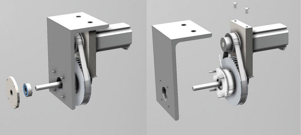
FIGURE 2. The axle is supported with an outer bearing. The outer bearing is trapped by an outer cover. The L frame is held in place with six fasteners.
The components for the 40-tooth drive pulley are visible to the right in Figure 5. The 40-tooth pulley is bearing-mounted on the shaft to rotate freely. Its bearing is captured between a retaining ring and the pillow block.
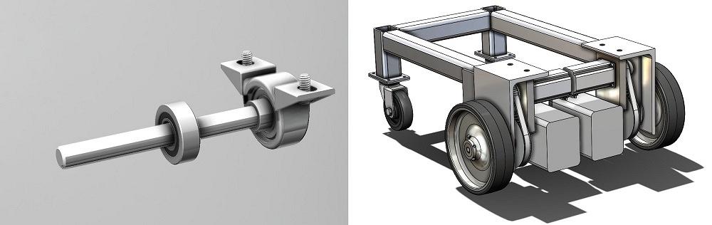
The bearings that directly support the axle are isolated to the left in Figure 6. The pillow block is setscrewed to the shaft. This controls the lateral motion of the shaft and allows it to rotate freely. The 40-tooth pulley with the friction pad/pole plate will slide laterally along the axle to release the clutch.
To the left in Figure 6, the batteries are shown tucked into available space. This progress model almost hit the size requirements. It is a little too wide because of the motors that were selected.
This demonstration of design review reveals the merits of detail in 3D modeling. Catching errors and omissions is never easy. The absence of models for the shaft keys might have been glaring in your review of my work.
A CAD goal was to use off-the-shelf components wherever practical. That strongly influenced the evolution of the custom-made components. The difference between the result in Figure 6 and the inspired cliffhanger from last month constitutes progress. To the extent that expectation and desire have been met, labor is complete.
Given a clear visual point of reference and a budget for available components, a steering committee convenes, while hanging on the proverbial cliff, to decide if these features and this cost are worthy of further development.
Of course, it is likely that an entirely off-the-shelf robot-cart drive system is available by the time this custom design can be assembled. The effort was not entirely wasted, however. At least decisions were made with certainty. Every product I’ve been involved with has been “designed” many times before a prototype came to be. Many prototypes followed. And everything in production gets revised.


The Fabricator is North America's leading magazine for the metal forming and fabricating industry. The magazine delivers the news, technical articles, and case histories that enable fabricators to do their jobs more efficiently. The Fabricator has served the industry since 1970.
start your free subscription
Easily access valuable industry resources now with full access to the digital edition of The Fabricator.

Easily access valuable industry resources now with full access to the digital edition of The Welder.

Easily access valuable industry resources now with full access to the digital edition of The Tube and Pipe Journal.

Easily access valuable industry resources now with full access to the digital edition of The Fabricator en Español.
Patrick Brunken, VP of Addison Machine Engineering, joins The Fabricator Podcast to talk about the tube and pipe...


