


Contributing Writer
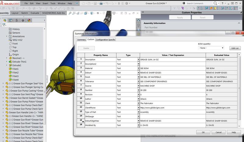
Figure 1
PMI stored in file properties may be viewed and edited with a table interface (File>Properties). Property names must be typed perfectly, usually from a CAD jockey’s memory. This is a difficult data entry interface to use without risking error. That’s why you want to learn how to use the Property Tab Builder.
Editor's Note: If you would like to download the 3-D CAD files associated with this column, click here.
Creating and editing product manufacturing information (PMI) is part of the CAD task. In some CAD systems, PMI is stored in the drawing file. In other mainstream 3D CAD systems, the drawings, tables, parts, and assemblies have a common mission: Display the PMI that is stored in the component’s file.
PMI is important. The design of forms to speed and simplify the collection of PMI does not need to happen often. The improved quality of PMI data collection makes form design worth the effort.
PMI may be created and edited while manipulating a 3D model. One free and easy method is to use the File Properties tool to edit PMI in a table format. A screen shot of such a table showing data for an imaginary grease gun is shown in Figure 1. While this table is useful for copying and pasting of properties between files, a CAD jockey could find it cumbersome to design in the graphics area with this table open. The issues with operation of the file properties table as a user interface include the opportunity for typing errors and the difficulty in perfectly recalling property names.
Here is a disclaimer: No actual grease guns were harmed in the production of this demonstration. Any resemblance to an actual grease gun is merely kismet. A specific brand of mainstream 3D CAD software is demonstrated. By the way, this 3D model uses a CAD technique of modeling with virtual parts to store all components in a single file on disk; separate component files are generated only when 2D drawings are needed.
Instead of using an awkward table to enter and edit PMI, a data entry form—examples shown in Figure 2—can be used to edit PMI in a goof-resistant workspace. The benefit is that everyone on the project uses the same forms. The form, unlike table-operating CAD jockeys, always uses the same property names and can provide drop-down lists to speed data entry as well as to reduce, and perhaps eliminate, typing errors. These PMI forms work well in combination with the Graphics Window.
In Figure 2 the 3D model can be seen in the Graphics Window. To the right of the Graphics Window, the Task Pane has the Custom Properties Tab (one of several available tabs) selected. The Custom Properties Tab is being described in this article as the “PMI form.” In this illustration, three screens shots are available for comparing alternative PMI forms for the grease gun. These alternative PMI forms are based on design decisions regarding source of labor. As a product is being designed and developed, the actual finished product could be custom-made and assembled by a subcontractor, purchased already assembled from a variety of common sources, or assembled in-house.
As may be noted in Figure 2, the displayed form on the CAD workstation is pretty narrow. Not much of it is readable without scrolling the form up or down. To help with this issue, conditional logic in the form’s design can be used to control what the form looks like.
The PMI form shown in Figure 2 has a “radio button” that allows the selection of one of three options for the type of assembly. A mouse click on the radio button does two important things:
Of the three manifestations of this form shown in Figure 2, the subcontracted option is leftmost, the common off-the-shelf assembly PMI is shown in the middle screen shot, and the in-house assembly data is shown rightmost. The space-saving form design idea is that details like tolerance and deburr matter for some things, and vendor part number matters for others. So display them only when they are pertinent.
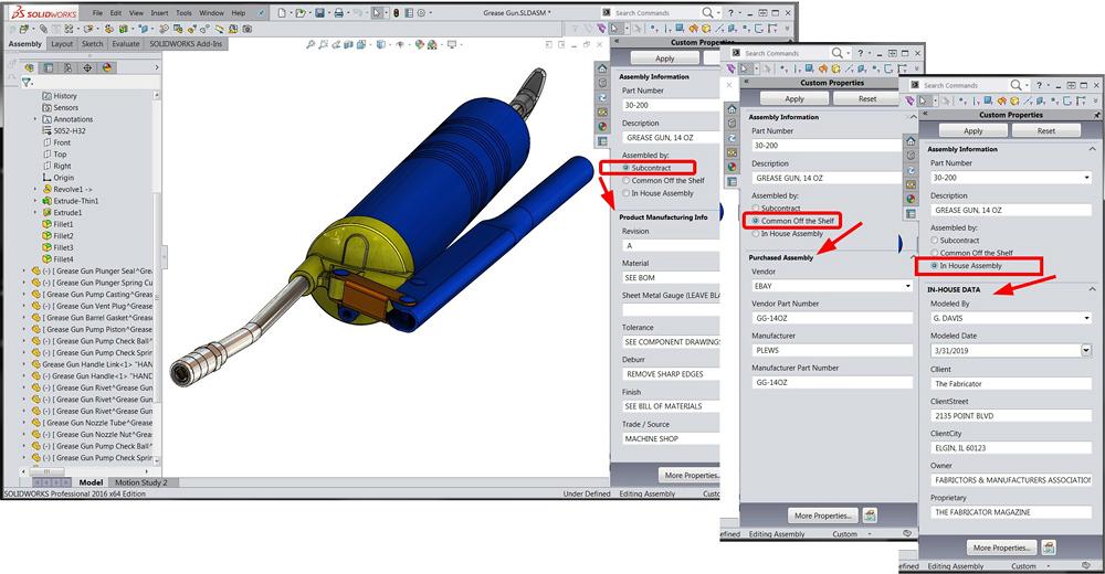
Figure 2
In real life, assemblies can be put together on a custom basis, or they might be purchased already assembled. Yet another possibility is that they could be assembled in-house. The PMI form has a radio button for that. The form can be designed to change to display only the right stuff.
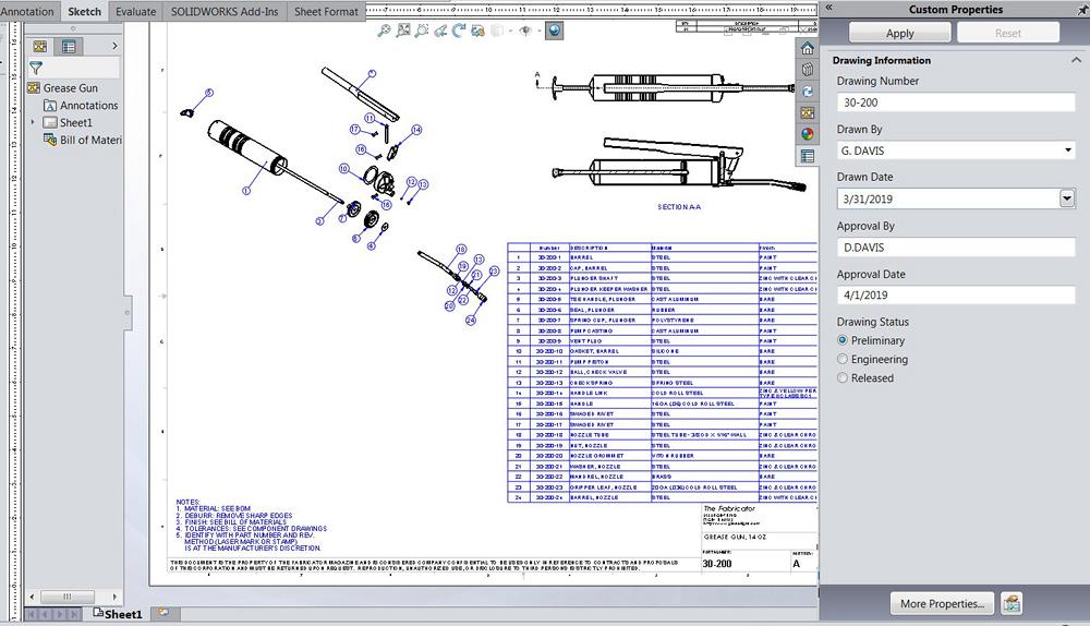
To emphasize the usefulness of PMI stored for retrieval, a drawing with a bill of materials (BOM) table is shown in Figure 3. The drawing is a tool to present the PMI stored in the grease gun model. Not only is the BOM table created automatically with information that is stored in the grease gun model, the title block is auto-filled with material, tolerance, and other tidbits of PMI. As shown to the right of the Graphics Window, the PMI form for a drawing file collects distinct PMI from that of the assemblies or parts is it presenting.
As a side note, the Custom Properties Tab is programmed to monitor what type of component has been selected. If an assembly is active, then the tab displays an assembly PMI form for that assembly. Similarly, a part displays a form designed for part PMI, and a drawing triggers the presence of yet another pre-prepared form.
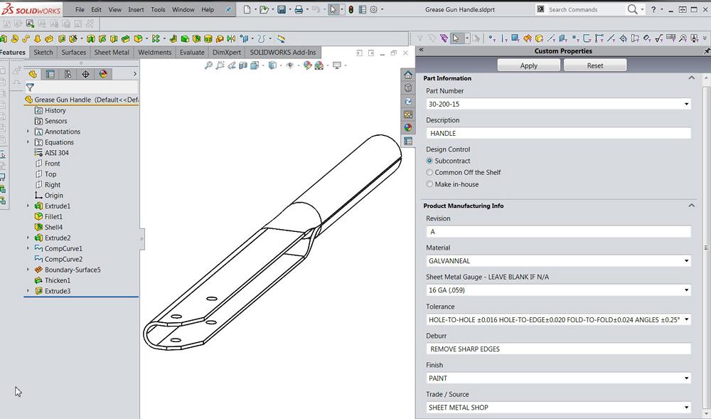
Emphasis has been placed on data collection tools because PMI matters. Where Figure 2 is using an assembly to review PMI, a part can be used just as well.
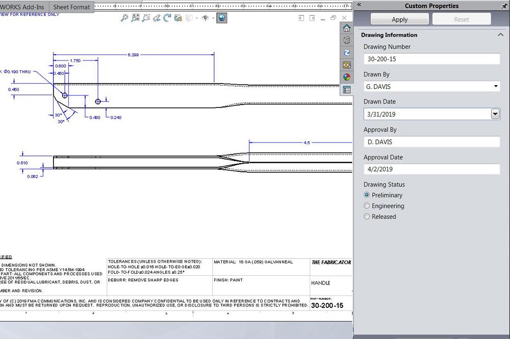
Figure 4a shows a part file—the pump’s handle. As with the assembly form, this part form has a radio button in its design to keep the form small and tidy. In Figure 4b a drawing, as opposed to a part or assembly, is showing PMI.
The PMI forms are designed with a tool named Property Tab Builder. To use the forms created in some known folder with Property Tab Builder, use the file location of that known folder retaining your personally designed PMI forms.
A zip is available for download that includes the three PMI forms used in this article—asmprp, prtprp, and drwprp. It also includes templates with matching file properties to the forms—asmdot, prtdot, and drwdot. And, of course, for the drawing template there is a sheet format—slddrt.
Gerald would love for you to send him your comments and questions. You are not alone, and the problems you face often are shared by others. Share the grief, and perhaps we will all share in the joy of finding answers. Please send your questions and comments to dand@thefabricator.com.


The Fabricator is North America's leading magazine for the metal forming and fabricating industry. The magazine delivers the news, technical articles, and case histories that enable fabricators to do their jobs more efficiently. The Fabricator has served the industry since 1970.
start your free subscription
Easily access valuable industry resources now with full access to the digital edition of The Fabricator.

Easily access valuable industry resources now with full access to the digital edition of The Welder.

Easily access valuable industry resources now with full access to the digital edition of The Tube and Pipe Journal.

Easily access valuable industry resources now with full access to the digital edition of The Fabricator en Español.
Patrick Brunken, VP of Addison Machine Engineering, joins The Fabricator Podcast to talk about the tube and pipe...


