


Contributing Writer

Documenting design changes through proper CAD software channels and improving revision procedures are necessary to prevent confusion and production problems on the manufacturing floor. Getty Images
Editor's Note: If you would like to download the 3-D CAD files associated with this column, click here.
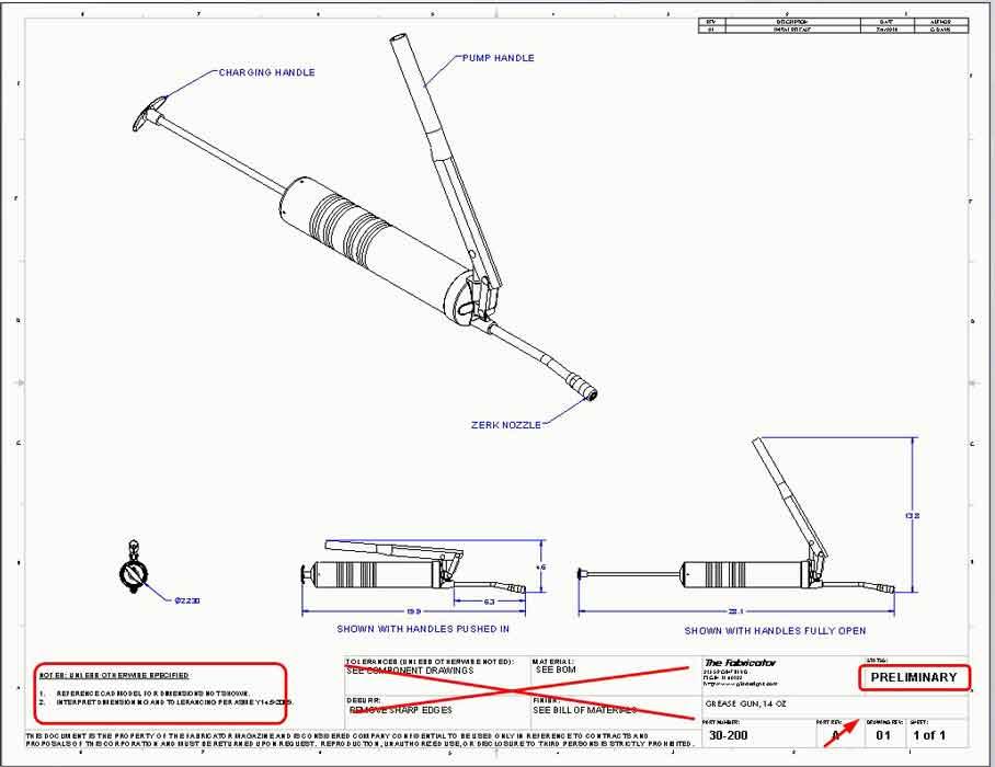
Last month, Figure 1 first appeared in the previous episode of this column (“Does your CAD work meet industry-defined standards?”). It has been marked up as an example of a drawing pending revision. In general, the creation of a 2D drawing with 3D CAD is an easy first step. The procedure might include assigning a file name and folder, designating a part number and making up a description, modeling the 3D part, and creating the 2D drawing.
Once that 2D drawing is completed, the next task, alas, is often revision of that drawing. Revision adds another layer of procedure. To help automate this task, document control add-ins for 3D CAD are available.
Here’s a CAD tip: It is possible to operate a document control system without add-ins like product data management or similar document management software. Don’t do that. Use a vault; it makes being a revisor much safer.
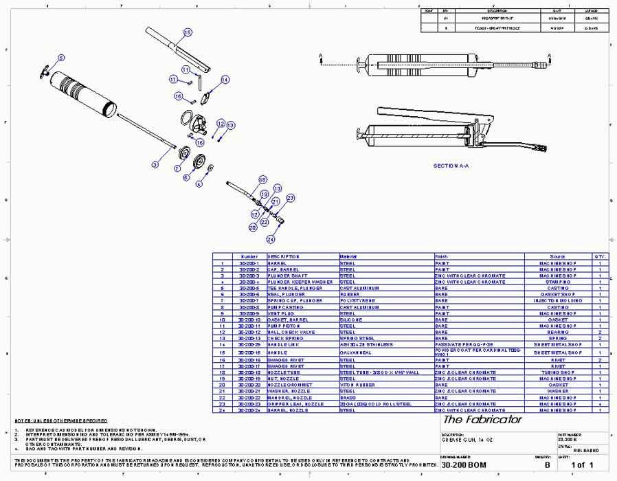
Figure 2 is an example of an arrangement-type drawing that needs improvement. Among other problems, it does not need to display material, finish, or deburr. The title block is too cluttered.
As we jump into changing things, take into account the many elements of a revision control policy and procedure. Furthermore, revision policies are tailored for individual businesses, so if your revision policy is different than ours, we’re interested but not surprised. Your comments and suggestions are appreciated.
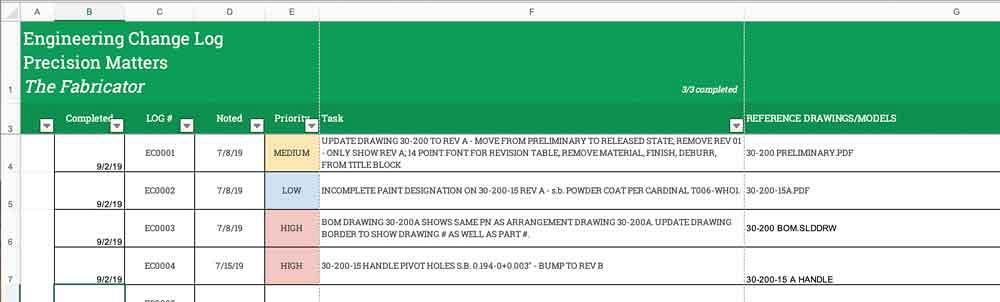
Our example revision procedure starts with a log, shown in Figure 3. Each discovered problem is assigned a unique engineering change number (EC#). In addition to the date of discovery, a description of the problem, a priority, and any known documents are recorded.
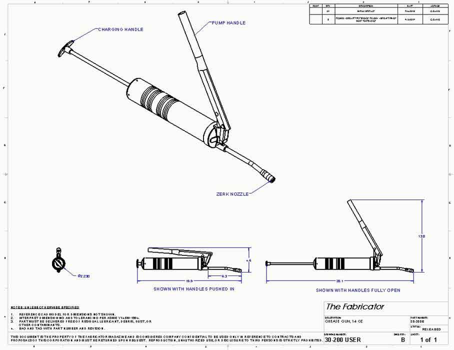
In Figure 3, we note that EC0003—a high priority—requires that drawings have an ID that is unique from the part being shown. This is because we have two drawings for the same item—a grease gun. One drawing is for end users, and the other drawing is for planners/assemblers. We need file names for both drawings and for the component they are showing. This will change the CAD department’s drawing template as well.
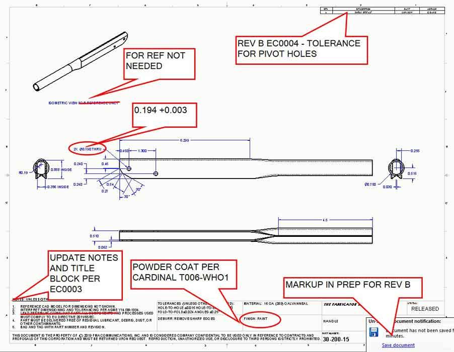
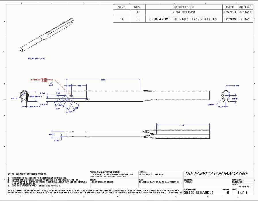
Our example revision procedure includes the markup of the drawing to show what is to be changed. See Figure 4a for an example markup drawing. In this example, three engineering changes are all happening at once—title block, hole size, and paint.
The markups from Figure 4a have been incorporated in Figure 4b. The red dimensions emphasize what changed in REV B. The new drawing title block shows both the drawing number (same as the drawing file name) and the part number of the item in view. The part number comes from product manufacturing information stored in the component in view.
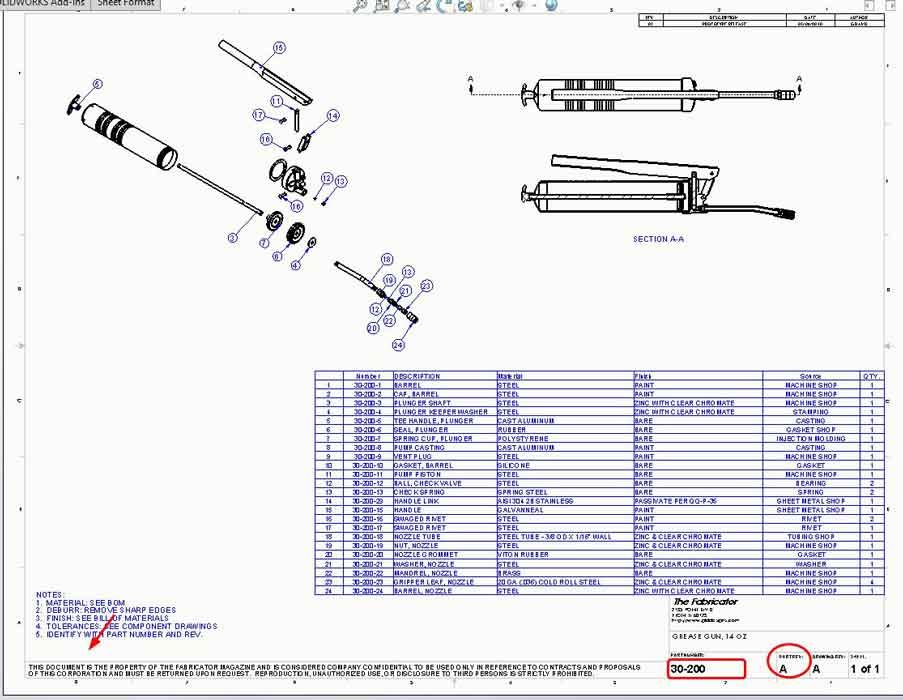
Figure 1
An example of an assembly-type drawing for a grease gun is shown. The drawing notes, title block, drawing number, and revision are to be changed.
Our imaginary drafting policy puts dimensions in layer DIM (shown as blue) and the component in view in layer NONE (shown as black). We also include a revision table in the upper right corner of the drawing. We take advantage of a software feature; revision tables automatically update the zone column when the revision symbols are placed on the drawing.
Our revision symbols are triangular. Those, along with the title block and updated notes, are saved in the new sheet format template. The new sheet format was applied to the drawing template so that future drawings will start out nicely.
For the existing drawings, the new sheet format is applied with a few mouse clicks to update the title blocks and notes. Our policy to use color requires a bit more clicking. Dimensions that changed this revision are moved to the REVISION layer, shown in red. All other dimensions from previous revisions are moved to the DIM layer. The use of layers makes color change easy.
The drawing in Figure 1 has been revised in Figure 5 with a new title block, improved revision table, and improved notes. Likewise, the drawing in Figure 2 has been revised in Figure 6. Unlike Figure 4b, not much shown is in red because the entire title block would show mostly red.
The use of color to emphasize what changed is very fancy and is probably a waste of effort. However, in some cases it does make it very easy to see what changed.
The use of revision symbols is recommended practice. Any shape symbol is fine, but we like triangles. The use of a zone column in the revision table is handy, especially on multisheet drawings. It is very convenient having the software do the data entry.
Read more from the Precision Matters series. Gerald Davis would love for you to send him your comments and questions. You are not alone, and the problems you face often are shared by others. Please send your questions and comments to dand@thefabricator.com.


The Fabricator is North America's leading magazine for the metal forming and fabricating industry. The magazine delivers the news, technical articles, and case histories that enable fabricators to do their jobs more efficiently. The Fabricator has served the industry since 1970.
start your free subscription
Easily access valuable industry resources now with full access to the digital edition of The Fabricator.

Easily access valuable industry resources now with full access to the digital edition of The Welder.

Easily access valuable industry resources now with full access to the digital edition of The Tube and Pipe Journal.

Easily access valuable industry resources now with full access to the digital edition of The Fabricator en Español.
Patrick Brunken, VP of Addison Machine Engineering, joins The Fabricator Podcast to talk about the tube and pipe...


