


Contributing Writer
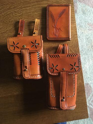
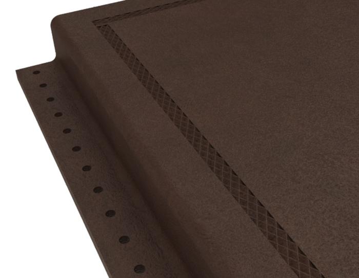
Figure 1a
3D CAD was used to make a flat pattern for a tall bike bag. The original kit (left) was too short to hold a passport book cover.
The old saw “When you have a hammer everything looks like a nail” applies to 3D CAD and leathercraft. Figure 1a shows results of a 3D CAD pattern for a taller version of a bike bag. The original kit (on the left) was too short to hold the passport book. It was reverse-engineered in the flat and then stretched to make the required patterns.
The time-saving CAD trick used was the Curve Driven Pattern to lay out the stitching holes for the front panel of the bag. This is shown in Figure 1b.
The hole pattern is set to a constant spacing of 6 mm. That dimension matches the stitching punch at hand. The location of the first hole and the length of the centerline path were adjusted to achieve artistic symmetry.
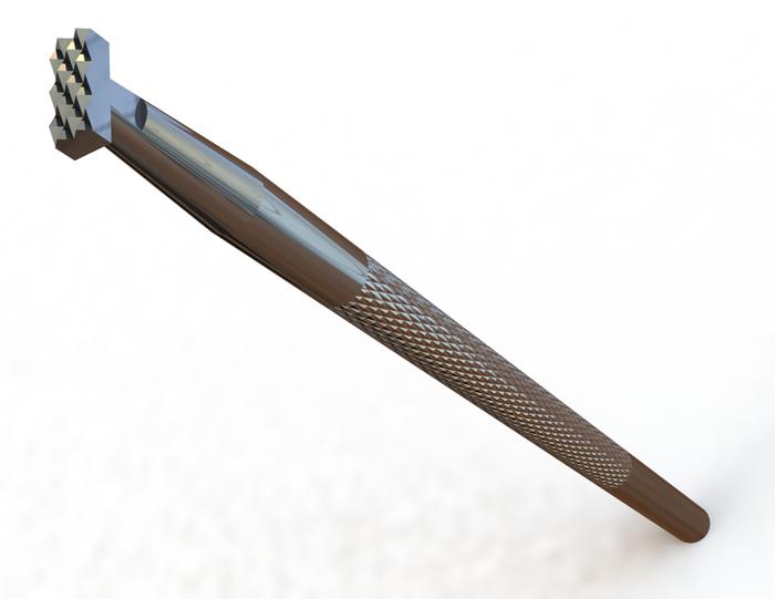
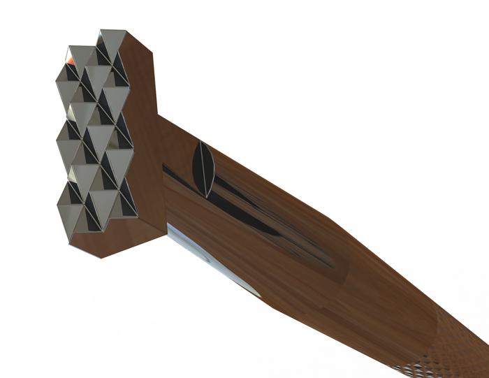
Figure 2a shows a faithful 3D model of a Craft Tool® A889. I purchased one of these from Tandy™ and used it to make the border on the passport book shown in Figure 1a.
The original design intent for this 3D model was for planning tooling patterns. The minimum requirement was the rectangular perimeter of the embossing pattern. I had no immediate need for the teeth, but they were fun to model. The additional modeling of the handle (using Single Revolved Sketch) and stamped part number were entirely due to obsession with detail. The result is useful for visualization.
Here’s a CAD tip: To save mouse clicks, the knurl is “rendered” as opposed to cut-extruded. A surface was created using Split Face, and then the appearance of that face’s Surface Finish was set to knurl. The scale of the knurl approximately matches the actual tool.
Figure 2b shows a roundness rendering trick. Round Sharp Edges is an appearance setting; in this example, 0.002 in. was applied to soften the edges to resemble the actual nickel-plated tool. As an alternative to rendered roundness, the diamond pattern of teeth has many edges and is very tedious to fillet as a solid body.
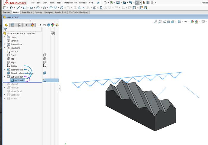
This example has teeth that were modeled as manufactured—a V cut with a 45-degree end mill. The CAD setup is shown in Figure 2c. Those V cuts were then mirrored to create the diamond pattern. The fillet at the bottom of the V is easy to model at this stage in feature history. Adding the fillets after the diamond pattern is completed can be very frustrating.
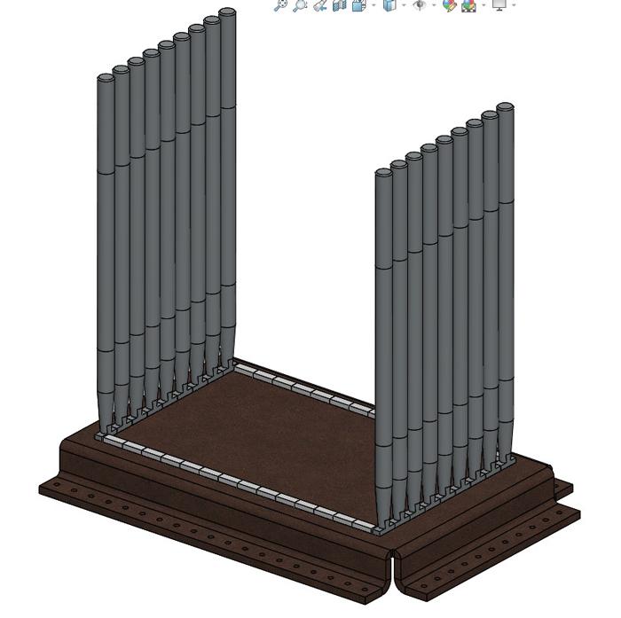
This example model of the tool (see Figure 3a) includes two configurations, one for visual accuracy and another for pattern layout. Sometimes you want a handle; sometimes you don’t.
This leather assembly (modeled as a sheet metal part) and stamping tool (modeled as a mold element) are useful for artful and efficient pattern experiments. Trial and error are very speedy compared to trying to do layout with a ruler and pencil.
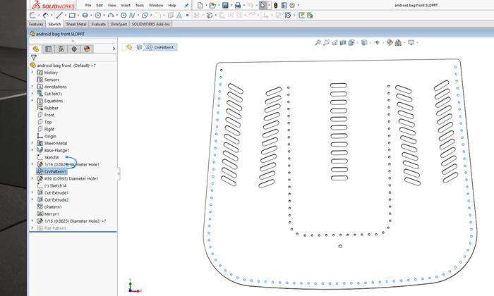
Figure 1b
The stitching holes are on 6-mm centers to match an on-hand leather punch. The Curve Driven Pattern uses a single hole and a sketched line to create a line of holes. The location of the first hole and the length of the line are adjusted for artistic result.
In addition to layout, this 3D CAD assembly makes it easy to model the finished leather for visualization. Figure 3b shows the leather part with the embossed pattern. The CAD trick is to edit the leather part in the context of the assembly while adding a Cavity feature to effectively subtract the patterned tools from the leather.
The “sheet metal” leather does unfold accurately in CAD. Leather is not quite as predictable as metal, so the tolerances must be adjusted dramatically.
Gerald would love for you to send him your comments and questions. You are not alone, and the problems you face often are shared by others. Share the grief, and perhaps we will all share in the joy of finding answers. Please send your questions and comments to dand@thefabricator.com.


The Fabricator is North America's leading magazine for the metal forming and fabricating industry. The magazine delivers the news, technical articles, and case histories that enable fabricators to do their jobs more efficiently. The Fabricator has served the industry since 1970.
start your free subscription
Easily access valuable industry resources now with full access to the digital edition of The Fabricator.

Easily access valuable industry resources now with full access to the digital edition of The Welder.

Easily access valuable industry resources now with full access to the digital edition of The Tube and Pipe Journal.

Easily access valuable industry resources now with full access to the digital edition of The Fabricator en Español.
Patrick Brunken, VP of Addison Machine Engineering, joins The Fabricator Podcast to talk about the tube and pipe...


