


Contributing Writer
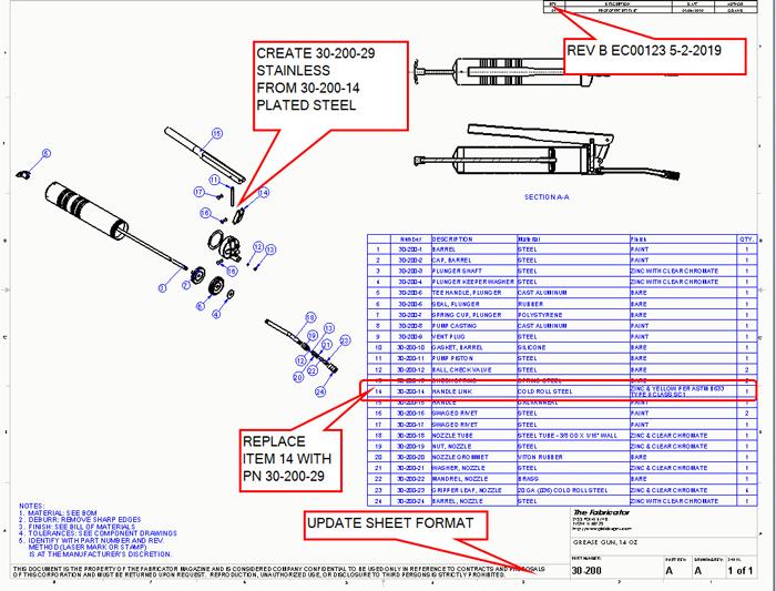
Figure 1a
In the realm of the sustaining engineer, document control can be as important as the information contained within the document. Continuous improvement, in the spirit of Eliyahu Goldratt, is part of the CAD task of producing controlled documents.
Change happens—even to final designs. Expansion of options in a product line is a common occurrence. Change has a cascading effect when you are trying to share common parts among several assemblies. The use of automated document management tools, often nicknamed “vaults,” makes the potentially complicated tasks of revision management relatively easy.
In addition to incorporating improvement to the product itself, the drafting standards applied to the product are likely to evolve. The information presented in the drawing border contributes to the cost of fabrication and ownership. Regulatory compliance, sensitivity to trade-specific terminology, change in ownership, change in CAD jockey, change in CAD software—all are examples of probable cause for drawing template improvement. The content and format of bill of materials (BOM) tables, revision tables, logos, and note styles also seem to change as soon as they are finalized.
Figure 1a shows an assembly marked up for change—a plated steel bracket needs to become a stainless steel bracket. In this example, the original plated version is to be retained for future use. Figure 1b shows the plated steel drawing marked up in preparation for creating the stainless steel part. Basically, create a copy of 30-200-24 and call it 30-200-29.
In some CAD systems, modeled parametric links are dependent upon file name, and sometimes upon file location as well. In addition to parametric links, components that make up an assembly are retrieved by file name. Therefore, to accomplish harmless change, you must take care to keep the CAD data happy.
If the goal is to merely rename a CAD file without launching the CAD system, you can use a specific tool developed for that purpose. When the CAD is installed, it adds an extension to Windows Explorer: Right-click on the component file, select CAD brand, and then select Rename. This is importantly different from using the ordinary Windows Explorer Rename tool in that parametric links are updated in related files.
As an alternative method of renaming, if the CAD system is launched with the assembly open, saving a component to a new file name effectively renames it for the assembly. Keep in mind that the drawing file for that component must be open as well, or it will not be updated to point to the new file.
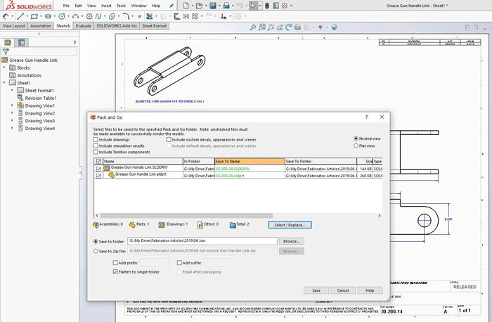
Perhaps the most versatile and goof-proof tool for harmless file name changing is Pack&Go. This tool may be launched either through Windows Explorer or via menu selection within the CAD software. Pack&Go can be used to create new file names and drawings based on existing components. Pack&Go has convenient tools for creating several files simultaneously.
The screen shot of Pack&Go in Figure 2 shows how the original drawing, along with the component it references, is being saved, while preserving all CAD pointers, to a new file name.
Here’s a side note that is solely the author’s opinion: When there is no higher priority, brief file names may improve the speed of CAD software. Unchanging file names are possibly labor-saving for CAD jockeys. Long file names may be human-friendly but take time for the CAD software to scan letter-by-letter while resolving parametric links. The inclusion of the revision in the file name is informative to humans, but when the component is shared by several assemblies, each of those assemblies must be updated to reflect the new, revised file name. As a labor-saving suggestion, consider that if the file name is not changed, then all modeled assemblies that use it still will open just fine any time.
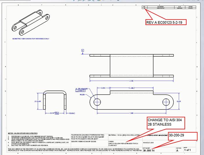
Figure 1b
When implementing a change, you have to make a choice between revision or new part number. Assignment of a new part number spawns a parallel line of history—a fork in the road. Such alternative component designs allow multiple versions of the assembled design to exist. Revision to components, on the other hand, replaces the previous design with a new one, so that only one version of the product exists.
A third choice exists, however.
This involves changing the design/drawing and not changing the revision. This would create multiple versions of the same part number with more than one revision. So long as the obsolete versions of the document are not permitted to get into production, this “let’s-keep-secrets” approach to revision-free document control might be OK.
Figure 2 shows Pack&Go set up to create a new set of files from existing files. This is a safe way to make a copy. For using that copy in the grease gun, the original link is replaced with the new one.
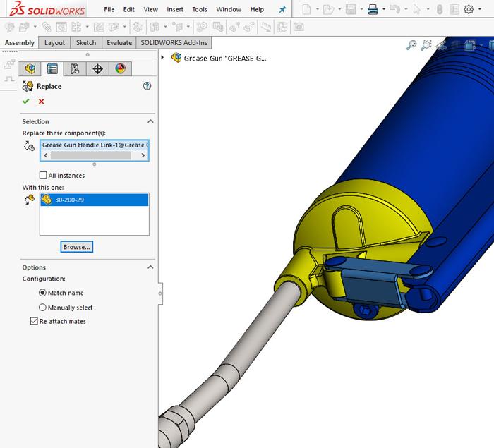
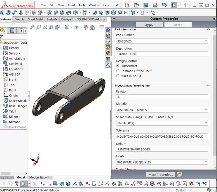
Figure 3a shows the Replace Component in action. Figure 3b shows the product manufacturing information (PMI) update in the new part file, with changes made to the material and the part number. The rest of the model was good to go. The drawing for the new link is opened in Figure 3c.
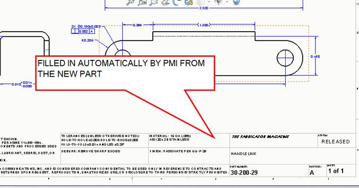
Because all of the CAD links were preserved, the title block for the drawing filled in correctly with the PMI from the stainless steel model. All that needed to be changed on this drawing was the revision block to show the correct history for this new part.
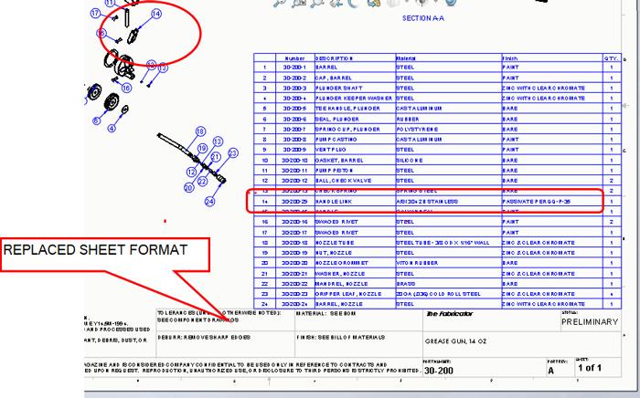
The grand finale is shown in Figure 4. The sheet format has been replaced by the author per the redline instructions in Figure 1a. Note that the CAD links to PMI caused the BOM table to update correctly. It actually took longer to type the explanation than it did to replace a component with a different one and keep all of the documentation updated.
Perhaps it would be fun to create a new option of the grease gun—a low-cost plated steel instead of a high-end stainless version for marketing purposes. That would be accomplished with a configuration table to switch between components instead of using the Replace Component tool.
Gerald would love for you to send him your comments and questions. You are not alone, and the problems you face often are shared by others. Please send your questions and comments to dand@thefabricator.com.


The Fabricator is North America's leading magazine for the metal forming and fabricating industry. The magazine delivers the news, technical articles, and case histories that enable fabricators to do their jobs more efficiently. The Fabricator has served the industry since 1970.
start your free subscription
Easily access valuable industry resources now with full access to the digital edition of The Fabricator.

Easily access valuable industry resources now with full access to the digital edition of The Welder.

Easily access valuable industry resources now with full access to the digital edition of The Tube and Pipe Journal.

Easily access valuable industry resources now with full access to the digital edition of The Fabricator en Español.
Patrick Brunken, VP of Addison Machine Engineering, joins The Fabricator Podcast to talk about the tube and pipe...


