


Contributing Writer

Figure 1c: The Attempt to Heal All button is almost always a good choice. If that doesn’t work, you’ll have to repair faulty features one by one.
Last month we explored using FeatureWorks® to transform a 3-D concept model into a 3-D production model. From that model we were able to produce flat layouts, but the main objective was to produce a good 3-D model that would be useful over the project’s lifetime.
But what if you don’t care about the 3-D model? What if all you want is a flat layout for CNC programming? Let’s explore that premise.
Before we go any further, let’s start with the usual disclaimer that we’re examining functionality that is unique to SolidWorks®.
For this exercise, we will start with a file in IGES format. The acronym is derived from Initial Graphics Exchange Specification. If we opened our starting file—SL2IC.IGS for example—with Notepad, we would see that it contains text in a very specific format. It does not have much meaning to the typical human. 3-D CAD software, however, is able to interpret that formatted IGES text and produce a 3-D model from it.
We could have just as easily started with a STEP file, another file standard. For sheet metal work, either will do just fine.
In Figure 1a we see the start of the process for importing the IGS file into SolidWorks. I clicked on File>Open then changed the file type to IGS. I then went to the folder where I had saved the IGS file to import. I selected the file SL2IC-0001.IGS and clicked on the Open button.
After I open the IGS file, the system produces a preview image of the 3-D model, along with the message shown in Figure 1b: “Do you wish to run Import Diagnostics on this part?” The process of converting IGS data into SolidWorks features may produce features that look right but function wrong; the Import Diagnostics process provides a means for you to help the software figure out what is right.
Figure 1c shows the Attempt to Heal All button. That is always my first choice. Let the software do its best. If that doesn’t work, then I’ll experiment with fixing, deleting, and re-creating faces until the model knits well into a solid.
Fortunately for this example, the software is able to make sense out of all of the IGS data, and we see in Figure 1d that no faulty faces or gaps remain in the geometry. I’m always happy to see that message with the green background.
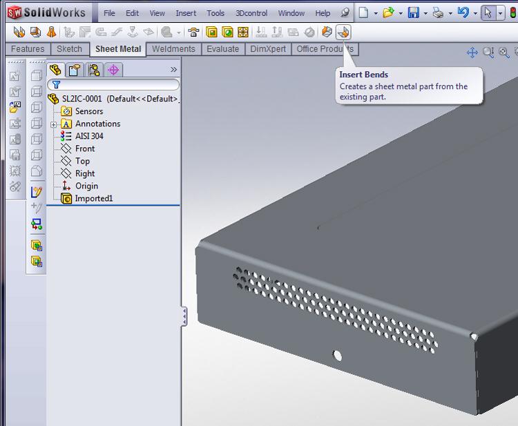
Now that we have the data imported, we have a “dumb solid“ with practically no feature history. That gives us a warm and fuzzy feeling, but our goal is to unfold the sheet metal part—maybe to change the bend radius, thickness, and bend compensation to match our tooling—and export a flat pattern. To do that, we need to convert this dumb solid into sheet metal. We’ll start doing that by inserting bends as shown in Figure 2a.

Figure 1b: Import Diagnostics will help you to remove faulty faces and gaps from the imported model.
On the Sheet Metal menu bar you’ll find an Insert Bends tool. After you click on that tool, you’ll be asked to select a fixed face. This can be any face of your choosing. When the software unfolds the part, the fixed face will remain stationary, and the other faces will swing and unfold around it.
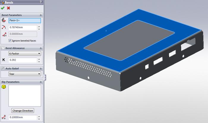
In Figure 2b I’ve arbitrarily selected the largest face as the fixed face. I also could change the value for the inside bend radius: 0.787 mm is about 0.030 inch, which should work well for the 22-gauge (0.030-in.) stainless steel that this is made from. A K-factor of 0.392 works with my press brake tooling on this material, but your shop might need to use a different value. (The K-factor is used to reference the neutral axis in a bent form, the line in a bend where the metal is neither compressed like the inside surface of the bend nor stretched like the outside surface of the bend. More specifically, a ratio of the location of the neutral line to material thickness determines the K-factor for a bend.)
After completing the Insert Bends, we arrive at Figure 3a, and we’re about to flatten the part to verify that our effort is going well. Before we do that, let’s check out the Feature History.
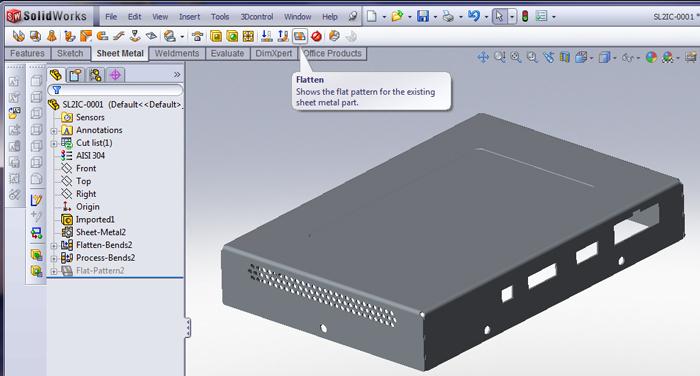
We started with an imported model—Imported1—and then added a Sheet Metal feature, a Flatten Bends feature, and a Process Bends feature. Note that the Flat-Pattern feature is suppressed while the part is folded. To unfold the part, the Flat-Pattern feature needs to be unsuppressed.
To make the toggling of the suppressed state of the Flat-Pattern feature more convenient, use a tool on the sheet metal menu called Flatten. All it does is toggle the suppression state of the flat pattern.
Figure 3b shows the result of clicking on the Flatten tool to flatten the part. Note that the Flat-Pattern feature is no longer suppressed, and the part unfolds correctly.
After measuring the flat to verify that the K-factor is set correctly, we also scan the part to ensure that all appears to be as expected. If necessary, we would edit the Sheet Metal feature to change the K-factor or bend radius.
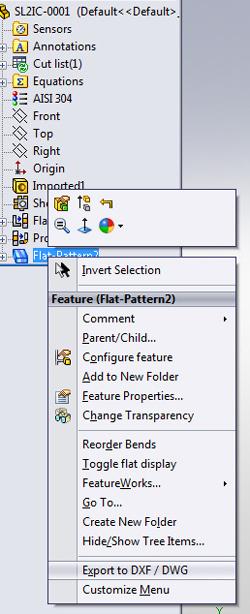
Now that we have a good flat pattern, we need to export it as a DXF file to the CNC programming software. To create the DXF file, I right-click on the Flat-Pattern feature in the Feature Manager’s history list. Figure 4 shows the pop-up menu that appears. Toward the bottom of the menu, an Export to DXF/DWG option can be found.
To review the process, we import an IGS file, verify that the resulting model has no faulty faces or gaps, insert bends, verify that the model will unfold as expected, and export a DXF for use with the CNC software. It actually took longer for me to type that sentence than it did to do the CAD work.
Gerald would love to have you send him your comments and questions. You are not alone, and the problems you face often are shared by others. Share the grief, and perhaps we will all share in the joy of finding answers. Please send your questions and comments to dand@thefabricator.com.

Figure 1d: Once the faulty faces and gaps are gone, you’ll see a message with a green background. Celebrate this moment of joy.


The Fabricator is North America's leading magazine for the metal forming and fabricating industry. The magazine delivers the news, technical articles, and case histories that enable fabricators to do their jobs more efficiently. The Fabricator has served the industry since 1970.
start your free subscription
Easily access valuable industry resources now with full access to the digital edition of The Fabricator.

Easily access valuable industry resources now with full access to the digital edition of The Welder.

Easily access valuable industry resources now with full access to the digital edition of The Tube and Pipe Journal.

Easily access valuable industry resources now with full access to the digital edition of The Fabricator en Español.
Patrick Brunken, VP of Addison Machine Engineering, joins The Fabricator Podcast to talk about the tube and pipe...


