


Contributing Writer
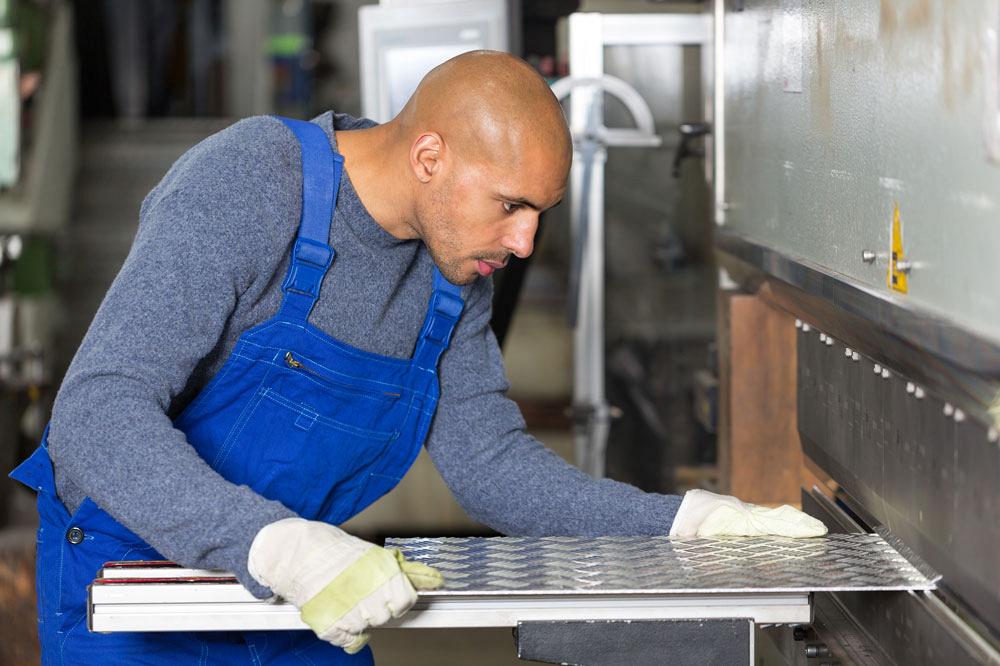
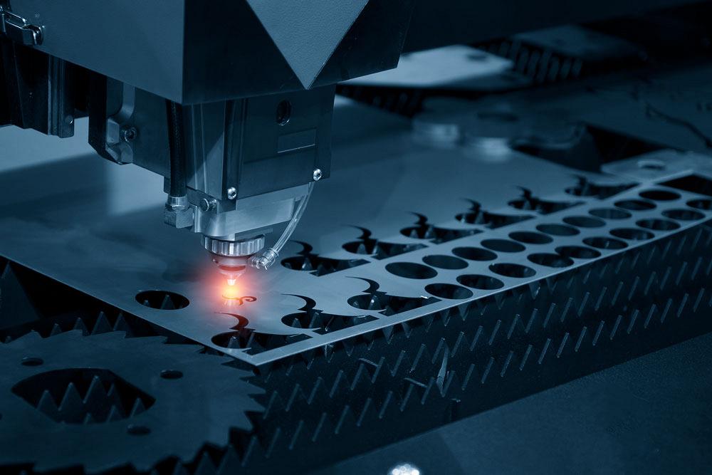
Figure 1
Goof-proof the design with symmetry when practical. Keep the fabrication process in mind when finalizing the design. Tooling and skill are both important to the result.
A reader recently asked for guidance in using 3-D CAD for designing sheet metal parts. The guidance offered here is partly related to design and largely related to communication. Once the “trade secrets” are revealed, the modeling choices become less mysterious.
Design for sheet metal—and design for manufacturability (DFM) in general—emphasizes the processes involved in fabrication. The goal is to optimize the product’s mechanical features to reduce the cost of production while maintaining the useful function of the product for the end user.
Here’s a shop tip: When bad designs emerge from the CAD department because of a misconception about how things are made, the fab shop might offer constructive feedback to improve the design. Shop tours also are recommended as a means to improve communication with CAD jockeys.
As a means of evaluating best practices in DFM in general, we offer two criteria: How easy is it to fabricate, and how well is it documented?
Accurate tooling, machinery, and a nice workpiece are represented in Figure 1. That is only part of the scene, however; skilled labor handles every part. Journeyman-level mastery requires years of study and improving applications. With enough skill, nearly anything can be described as “easy.”
Regardless of available skill, some designs are simply easier to build than others.
As an example of the close relationship between tooling and design, a bending process is shown in Figures 2a and 2b. This brake has two workstations set up in its bed. The right station is for long bends, and the left station—the one in use—is for shorter bends. In Figure 2a, two bends have been previously completed, using the tooling station to the right, and the part is being positioned in the tooling for a third bend. Note the close fit of the tooling between the two existing bends.
In Figure 2b the last of four bends is being completed. Fortunately for this design, the workpiece swings very close to, but does not hit, the tooling or the machinery.
Beyond skill, the fabrication trade includes process, as a combination of tooling and machinery. “Is suitable for fabrication using available tooling and materials” is a better criterion than “easy to fabricate.”
A design workflow with sheet metal-specific CAD techniques helps in at least three ways with documenting the product:
As an example of using sheet metal-specific CAD tools, Figure 3 shows a screen shot of a sheet metal design. The history of the sheet metal techniques used is shown on the left, and the product manufacturing information (PMI) is shown to the right of the graphics window.
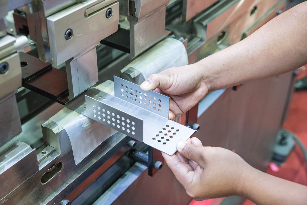
Figure 2a
Tooling matters to the design: Bending sequence three of four is shown. Note the close fit of the upper tool between the two existing bends in the workpiece.
Here’s a DFM tip: When it comes to pleasing those in manufacturing, how you model is not as important as what you model. With that said, the goal in this series of articles is to improve your CAD technique for sheet metal modeling.
Product designers make better decisions if they clearly understand the consequences of batch size and fabrication method to expense. A few phrases of terminology follow to set the stage.
Lot is sometimes used interchangeably with batch. While a lot charge might seem like a lot, the term refers to a fee that applies to the entire batch, regardless of quantity.
The fab shop’s production capability is constrained by its fabrication machinery and tooling. The fab processes in the production line might include shearing, laser cutting, punching, embossing, deburring, forming, welding, hardware installation, finishing, and packaging.
A factory might have a production line that never changes, such as that for a retail consumer item. Specialized tooling and extensive use of automation reduce the unit cost of production, although the initial startup cost is significant. As an optimized process with a single purpose, this production line seldom undergoes any change to the setup. Design revisions are typically very expensive to implement in the production line.
Figure 4 shows machinery and tooling being set up as part of a production line. A “job shop” is distinguished from a “factory” by how often the setups are changed.
Consider a segment of industry where changes to the production line happen frequently. What does a corn harvester have in common with an automated gated entry? The answer is a control box made from painted sheet metal. It’s a different shape, material, and color, but it’s made in batches by the same job shop. Such quick-change production facilities—the job shops—are better able to incorporate changes to the product’s design.
The job shop is a production line that is time-shared by many similar products. The same tooling and machinery are simply reprogrammed to make a variation rather than something entirely different.
In the following examples, the emphasis is on job shop lot production of parts. The fabrication of those parts is to be based upon the 3-D CAD master model.
During the inventing and designing stages, demand is clearly unknown for the not-yet-existing part. The product’s popularity with end users can only be predicted. With that said, prediction of production quantity and assembly schedule may help with DFM and material planning, for example, by constraining the size of the workpiece to achieve a quantity of parts nested on a sheet of raw material.
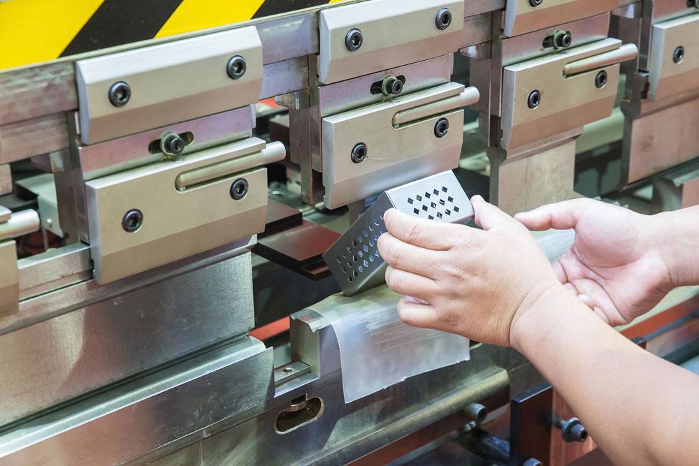
Figure 2b
Bending sequence four of four is completed. The workpiece swings very close to, but does not hit, the tooling or the machinery.
Each lot or batch of parts that is manufactured has a fixed, also known as a minimum, expense. This baseline expense includes material and labor required to set up the machinery to cut and bend the sheet metal.
After the setup has been completed, any number of identical parts can be fabricated. Bigger batches spread the setup cost out so parts appear to get cheaper the more you buy.
Here’s a DFM tip: Simplify the setup chore. Design around available tooling when practical. When the time between batches is short, a nonrecurring engineering (NRE) order for specially designed tooling and machinery for future demand may be a means to eliminate setup expense in a fully optimized design.
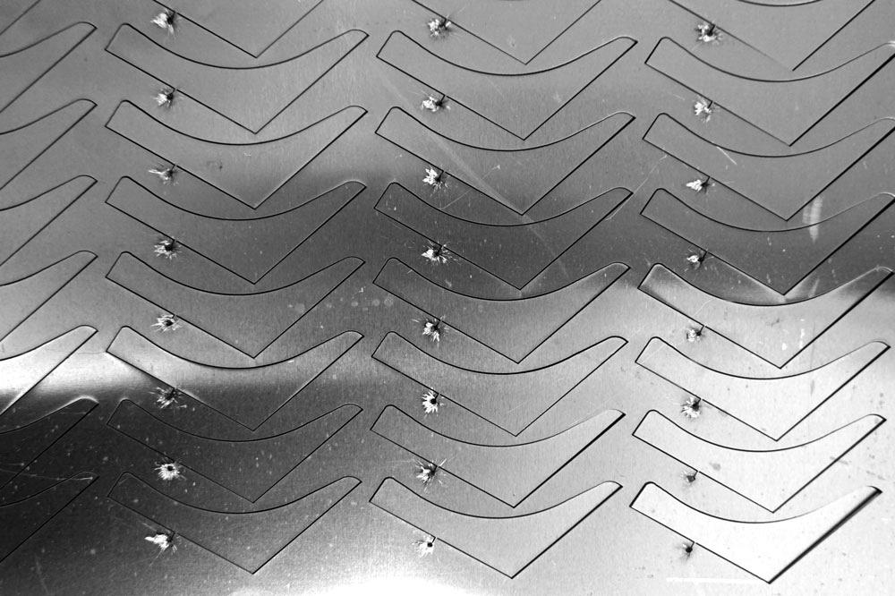
Figure 5 is an example of a small quantity of several different parts nested on a sheet of raw material.
The first production job might be for an order of just a handful of parts. This small lot is intended to proof tooling and the suitability of the parts for end use. Figure 5 is an example of how the job shop is cost-effective compared to a dedicated factory in producing small lots of first-time builds.
The unit cost of small batches of first-article items includes the cost of creating tooling, programming machine tools, writing up a production and quality control plan, and accounting for many other one-time or nonrecurring expenses. That NRE expense can make the unit cost of parts in small lots seem large.
Fortunately for the factory with a dedicated production line, the nonrecurring expenses of the first lot are … wait for it … absent in subsequent builds of the part.
Unfortunately for the batch business, setup is a significant and recurring expense. The cost of 10 batches of 10 is more than one batch of 100, largely because of repeated production setup. Some NRE items in the job shop, such as production planning and CNC programming/nesting, do exist. With any production line, any revision to the design triggers another round of NREs.
vAfter the first article is accepted, the fab shop’s job is to build a lot for initial distribution, say, 100 units. Driven by demand, the fab shop’s job is to build in lots of various sizes. The lot size—number of parts in the batch—is administered with the goal of predictable scheduling and minimum idle inventory throughout the year.Predictability in demand allows the job shop to behave more like a dedicated production facility, with the benefit of reduced setup and less wasted material, perhaps. Cost reduction is always good.
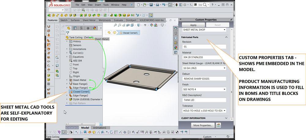
Figure 3
Sheet metal CAD tools are recommended because they clearly document the design intent and closely match actual fabrication steps.
One of the benefits of being able to produce a flat layout is the opportunity to anticipate how the workpiece will be cut from a raw sheet of metal. See Figure 6 for an example. Using a known raw stock sheet size as a starting point, we can see how the flat pattern of the workpiece can be overlaid or patterned in a nest to see how it fits. Sometimes several extra parts can be nested onto a single sheet of raw material by rotating the orientation.
The economic order quantity (EOQ) for a lot of parts is a function of how many parts are nested on the sheet minus a few for setup. During fabrication of each lot, a few parts are lost because of setup and process variation.
For example, 16 parts might be nested on a full sheet of raw material. It is likely that some, maybe four, of those starters will be lost while setting up the press brake or during painting.
If the production order is for 48 parts, that could be filled with exactly three full sheets, but does not provide any margin for error. To produce usable setup parts, the fab shop starts with four sheets that have 16 parts per sheet, which results in 64 parts. The shop will deliver 48 of those completed items. The fate of the extra 16, at various stages of production, is simply to become overhead expense. That’s not very economical.
With the idea that four parts are dedicated to setup for each lot, strategic purchasing and scheduling comes into play. If the starting production order were for 44 parts, then only three sheets with 16 nested flat blanks are needed instead of four sheets. That is an example of a smarter EOQ.
DIY nesting and EOQ analysis are examples of unusually detailed DFM and production planning. It is not always possible to know how parts will be nested on the sheet at the time of order. To make the best use of material, the fab shop might nest concurrent batches of other items sharing the same base material. The fab shop is the best source for information regarding EOQ.
Here’s a DFM tip: Goof-proof the design by making it difficult or impossible to form backwards or with incorrect grain direction. Symmetry reduces wasted material in the shop.
Thickness of raw stock sheet metal is an important topic. In the fab shop, standard gauges limit the cost-effective design choices. In the CAD shop, the sheet metal tools work with any thickness or geometry. These CAD tools can be used for modeling anything that is made from sheet, including plastic, paper, and cardboard.
In the fab shop, sheet metal generally is between 0.02 in. thick and 0.250 in. thick. Thicker than that, it becomes plate instead of sheet metal.
Tables are readily available to cross-reference decimal thickness and standard gauge thickness. Figure 7 is found online courtesy of Alaska Copper & Brass Co.
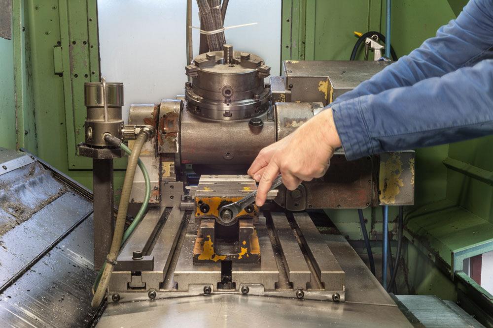
Figure 4
Set up of a production line is a significant expense. Some production lines are seldom changed once they are set up. Other production lines have their setups changed frequently, as in job shops.
Steel gauges are the same as those shown for stainless steel. For example, 16-gauge steel is 0.060 in. thick.
By tradition in the U.S., aluminum and other nonferrous materials use a gauge system (Brown & Sharpe) that is different from that used for steel and other ferrous materials (Manufacturers Standard Gauge). For example, B&S 16-ga. aluminum is 0.050 in., whereas MSG 16-ga. steel is right around 0.059 in. thick.
Sheet metal gauge tables must be read with their accompanying tolerance qualifications. For example, the tolerance might be +0 percent and -5 percent of the thickness. Using 16-ga. (0.059-in.) cold-rolled steel as an example, 5 percent is roughly 0.003 in., which means that 0.056 in. (0.059 in.— 0.003 in.) might be the actual thickness of the 16-ga. cold-rolled steel. It should not be too surprising that sheet stock is often rolled to the thin side of the advertised thickness range for each gauge.
Next month’s installment continues with the perils of creating sheets of metal and what uniform thickness means in the real world.
Contributing Writer Gerald Davis uses CAD software to design and develop products for his clients at www.glddesigns.com. From 1984 to 2004 he owned and operated a job shop. Gerald would love for you to send him your comments and questions. You are not alone, and the problems you face often are shared by others. Please send your questions and comments to dand@thefabricator.com.


The Fabricator is North America's leading magazine for the metal forming and fabricating industry. The magazine delivers the news, technical articles, and case histories that enable fabricators to do their jobs more efficiently. The Fabricator has served the industry since 1970.
start your free subscription
Easily access valuable industry resources now with full access to the digital edition of The Fabricator.

Easily access valuable industry resources now with full access to the digital edition of The Welder.

Easily access valuable industry resources now with full access to the digital edition of The Tube and Pipe Journal.

Easily access valuable industry resources now with full access to the digital edition of The Fabricator en Español.
In this episode of The Fabricator Podcast, Caleb Chamberlain, co-founder and CEO of OSH Cut, discusses his company’s...


