


Vice President
Editor’s Note: This article is adapted from Joseph Baldauff’s paper presented at Pipe & Tube Nashville 2012, June 26-28, 2012, Nashville, Tenn., © 2012 by the Fabricators & Manufacturers Association Intl. (FMA) and the International Tube Association (ITA).
Nondestructive test (NDT) methods used for tube or pipe have a critical limitation: They have difficulty testing all the way to the tube or pipe end. The limit usually is called the untested end. NDT systems have a transmitter that generates ultrasonic waves for ultrasonic testing or electromagnetic waves for eddy current or magnetic flux testing. A receiver senses the flow andtriggers an alarm when it detects a change in the flow, alerting the equipment operator that it likely has found a defect. The limitation is that the end of the tube or pipe causes an abrupt change in the way the ultrasonic or electromagnetic waves move through the tube or pipe. The receiver has difficulty making sense out of the information it picks up near the end, making the test results lessreliable as the receiver nears the end.
In some cases, cutting off the untested end is acceptable; in some applications, it isn’t. In fact, some industries require more stringent testing near the tube or pipe end because it will be expanded or threaded, and end integrity is critical to the product’s performance. In the case of tube for oilfield applications, threaded ends can fail if lamination or mechanical defects exist at thetube ends. In this type of application, cutting off the untested end does not meet the final requirement.
A new testing concept, one that uses several transducers that concentrate sound waves into a small tube coupon area, can test tube and pipe near the ends successfully.
The system relies on many of the principles used in other ultrasonic test systems. It rotates the tube to carry out the test and uses water as the coupling medium. The testing location is at the bottom of the tube, where gravity causes the water to accumulate.
This system is different from a standard system in that it uses a large number of transducers in a small area. Crowding the transducers together normally is avoided to prevent interference with each other when doing high-speed, full-body testing. However, because this system uses a tube rotation rate that is slower than normal, approximately 3 to 5 revolutions per second, the pulse repetitionrate can be standardized at 1 kHz and all transducers can be pulsed relative to this rate. Any transducer-to-transducer interference can be eliminated by the standard delay function that is built into the pulser/receiver. A 1-kHz pulse rate allows 500 microseconds of delay, which can be split up in any combination.
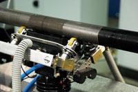
The transducer box contains a total of three two-element transducers; the two elements are for CW and CCW circumferential interrogation (see Figure 1). The central device is used for wall thickness and lamination testing. The four outer devices are for forward transverse and reverse transverse testing.
Diameter Changeover. Rather than relying on the operator to make changes in the setup when changing to a new pipe or tube diameter, with this method a diameter gauge is used to adjust the tube follower roll set to keep the distance from the transducer to tube surface constant. This keeps the sound entry point constant, which keeps all angles and the sound path constant. This nearly eliminatesthe need to make adjustments to the transducers, greatly reducing changeover time.
Material Handling. The tube is transferred to the test system by a walking beam transfer device. As the tube moves into position, mandrels at at each end engage the tube and seal it. The transducer box moves into position at the bottom of the tube; an air spring applies pressure to hold the transducer unit in the correct position. The rollers keep the transducers a constantdistance from the tube or pipe wall.
Bowed Tube or Pipe. The transducer array is mounted to a flexible structure that allows it to follow the bow in material that is not straight. This prevents erroneous readings that would result from a coupling loss.
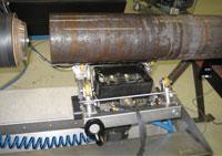
Figure 1.The clockwise (CW) and counterclockwise (CCW) transducers are shown at the minimum and maximum angles. The transverse transducers are pointed at the same location as the CW and CCW devices.
Transducer Slew Rate. The transducer box’s slew rate depends on the tube OD and the tube rotation rate. The operator enters the OD; an encoder determines the rotation rate.
Pitch. The transducer’s motion must be coordinated with the rotational speed of the pipe; the pitch is the distance the transducer moves during each complete rotation. This must be tightly controlled to obtain full volumetric coverage and to optimize repeatability.
Skew. Skew is the roll angle needed to obtain zero friction and minimal roll wear.
Two standard tubes were tested and evaluated: seamless tubes that measured 6 5/8 in. OD by 0.78 in. wall thickness (168 mm by 20 mm) and 2 7/8 in. OD by 0.020 in. wall thickness (73 mm by 5 mm).
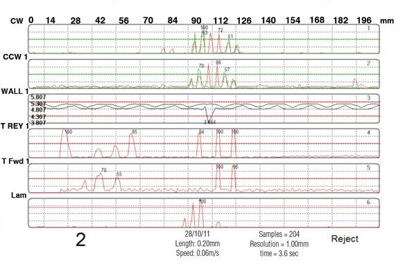
Notches. Both tubes had longitudinal and transverse OD and ID notches, 1 in. (25.4 mm) long and 5 percent of the wall thickness deep. The longitudinal notches were located 4 7/16 in. (112.5 mm) from the tube end; the transverse notches were located 2 in. (50.4 mm)from the tube end.
Holes. Both tubes had a 1/4-in.-(6.3-mm-) dia. flat-bottom drilled hole (FBDH) located in the same plane as the notches. The holes were 50 percent of the wall thickness.
Testing time. The testing time for small tube was approximately 4 seconds; testing time for large tube was approximately 8 seconds. The test time is an inverse function of the rotation speed capability, so it depends on the OD.
Testing area. The length of the tested tube end was approximately 10 in. (250 mm).
The heart of the system, the transducer carrier, has enough flexibility to accommodate a variety of tests and configurations. In addition to ultrasonic, it can be outfitted for eddy current and magnetic flux leakage testing. It also can be configured to test the entire tube length (commonly called full-body testing).
Finally, the carrier can work with a gantry system, in which the probes are located above the item under test. This sort of setup often is used for testing large-diameter bar or tube. See Figure 2.


The Tube and Pipe Journal became the first magazine dedicated to serving the metal tube and pipe industry in 1990. Today, it remains the only North American publication devoted to this industry, and it has become the most trusted source of information for tube and pipe professionals.
start your free subscription
Easily access valuable industry resources now with full access to the digital edition of The Fabricator.

Easily access valuable industry resources now with full access to the digital edition of The Welder.

Easily access valuable industry resources now with full access to the digital edition of The Tube and Pipe Journal.

Easily access valuable industry resources now with full access to the digital edition of The Fabricator en Español.
In this episode of The Fabricator Podcast, Caleb Chamberlain, co-founder and CEO of OSH Cut, discusses his company’s...


